21
Parts & Service: 020 8988 7400 / E-mail: Parts@clarkeinternational.com or Service@clarkeinternational.com
dependant upon the cutting tool profile, as profiles differ from thread to
thread.
For detailed information regarding screwcutting techniques, cutting tools etc.,
you should consult a suitable handbook or obtain advice from a qualified
person.
A leadscrew, with corresponding half nuts and thread dial indicator, for the
production of Metric threads is available from your Clarke dealer, see
‘Accessories’ on page 30.
The general procedure for screwcutting is as follows:
1. Try to get as much distance from the chuck to the end of the proposed
screw thread as possible and if your design allows, cut a ‘run-off’ into the
work which is of a smaller diameter than the root diameter of the proposed
screw thread. Note that for long threads it may be necessary to use
‘steady’s’ (see Accessories’ on page 30).
2. Install the appropriate gears for the thread required and correctly mount
the cutting tool.
3. Set your required depth of cut and position the tool ready to begin cutting.
NOTE: Depth of cut is vitally important and may be calculated or obtained
from an appropriate reference manual.
4. Take all necessary precautions
previously stated and start the
lathe with the automatic feed
lever in its disengaged position
(UP).
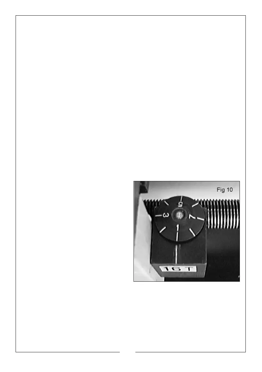
NOTE: Mounted on the Apron,
adjacent to the Auto Feed
Lever is the Thread Dial
Indicator, shown in fig. 10. This is
permanently connected to
the leadscrew and as the
leadscrew turns, the ‘dial’
rotates. Eight radial marks are
etched on the dial and these
are used to determine the
exact position of the leadscrew thread in relation to the saddle.
• Mounted on the front of the gear train cover is the Indicator Table,
which is duplicated on page 25. The numbers in the ‘SCALE’ column
refer to the numbers on the radial lines on the Indicator Dial. Therefore, if
a 20TPI thread is to be cut for example, the marks 1,3,5 or 7 may be used.
You should now proceed as follows:
 Loading...