26
Parts & Service: 020 8988 7400 / E-mail: Parts@clarkeinternational.com or Service@clarkeinternational.com
.
In order to change the gears ensure the machine is switched OFF and
disconnected from the mains supply.
Remove the gear train cover which is secured with two socket head screws.
Gear A may be considered as the driver and Gear D as the driven gear.
When a Simple gear train is configured as illustrated in Fig. A, page 24, the
gear at B acts as an Idler and its size is therefore irrelevant - any convenient
gear will suffice to connect A and D. This is denoted by a blank space in the
column in the gear chart.
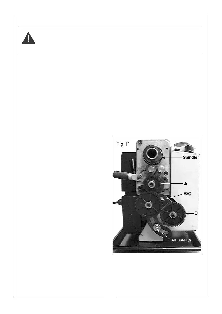
The positions of the shafts carrying gears A and D are fixed, therefore all
adjustments are carried out on the shaft carrying gears B and C and the
Adjuster ‘A’, shown in fig. 11.
1. Unscrew the hex socket head
screws securing gears A and D,
followed by the screw securing
gears B and C.
2. To allow the gears B and C to
disengage completely and to
provide for easier reassembly,
unscrew the nut securing the shaft
carrying B and C and the nut
securing the adjuster A.
3. Remove the gears, taking care to
retain the small keys on each shaft,
and replace with those necessary
to produce your screw thread.
They may be mounted either way
round.
• The number of teeth on each
gear is clearly marked.
Replace the securing screws, ensuring
the flat washer bears up against the gear hub in each case.
NOTE: If a compound gear train is required, as shown in Fig. B on page 18,
ensure the spacer, which is keyed to the shaft carrying gear D, is
located on the shaft, BEFORE the gear, in order to align gear D with gear
C.
WARNING: NEVER RUN THE MACHINE WITH THE COVER REMOVED.
 Loading...