10
Mounting the Mill Head
Remove the protective greased paper from the headstock mounting, and ensure
the surface is clean and undamaged.
• Carefully raise the Mill Head, noting that the plastic lower pulley cover is not fully
secured at this stage and is vulnerable. Very carefully lower the head on to its
mounting on the headstock. Secure with the four Hex socket head screws provided.
• If the cable to the microswitch has been disconnected, it should now be
replaced and the cable secured in the clamps on the side of the mill head.
• You will note that cable is secured with a clamp plate, adjacent to the pulley.
similar clamp is provided in the box of loose parts, and this should be screwed
in place adjacent to the Driven Pulley so that the lower pulley cover is properly
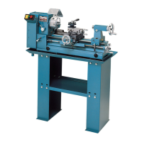
• Fit the Chuck Guard according to Fig.5.
CL500M: Remove the transit screw in
the base of the Mill Head from the
position arrowed at ‘B’, (if fitted).
Secure the Stop Bar ‘A’ with the screw
and flat washer ‘B’ found in the guard kit.
The screw attached to the Guard -
’C’ is threaded through the remaining
hole in the stop bar, and screwed into
the headstock....note the rounded
end of the stop bar is at the guard
pivot end...or to the right side.
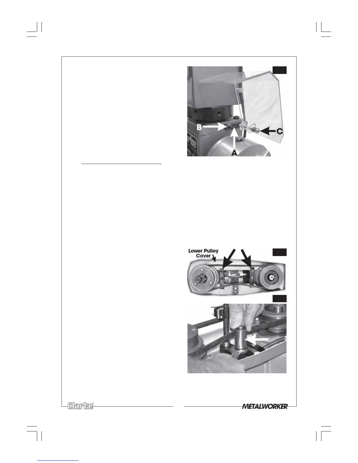
secured. Do not overtighten as this
will distort the cover.
Both clamps are arrowed in Fig. 6
• Slip the drive belt over the pulleys in the
manner shown in Fig 6.
• Slacken the nut securing the belt
tension roller as shown in Fig.7)
sufficient for the roller to be moved
inwards, in the direction of the arrow,
thereby applying tension to the belt.
Retighten the nut when the belt
may be deflected by approx. 1/2
inch, when applying reasonable
pressure, in the middle of its run
between the pulleys.
• Place the pulley cover in position and
secure with the large knob provided.
NOTE: It is important to ensure that the
microswitch is activated when the cover
Fig.7
Fig.5
is in place. If you do not hear an audible click when the cover is lowered into
place, you must remove the cover and raise the microswitch, on the rod, until a
click is heard when the cover is replaced. Ensure the microswitch is properly secured.
Fig.6