8
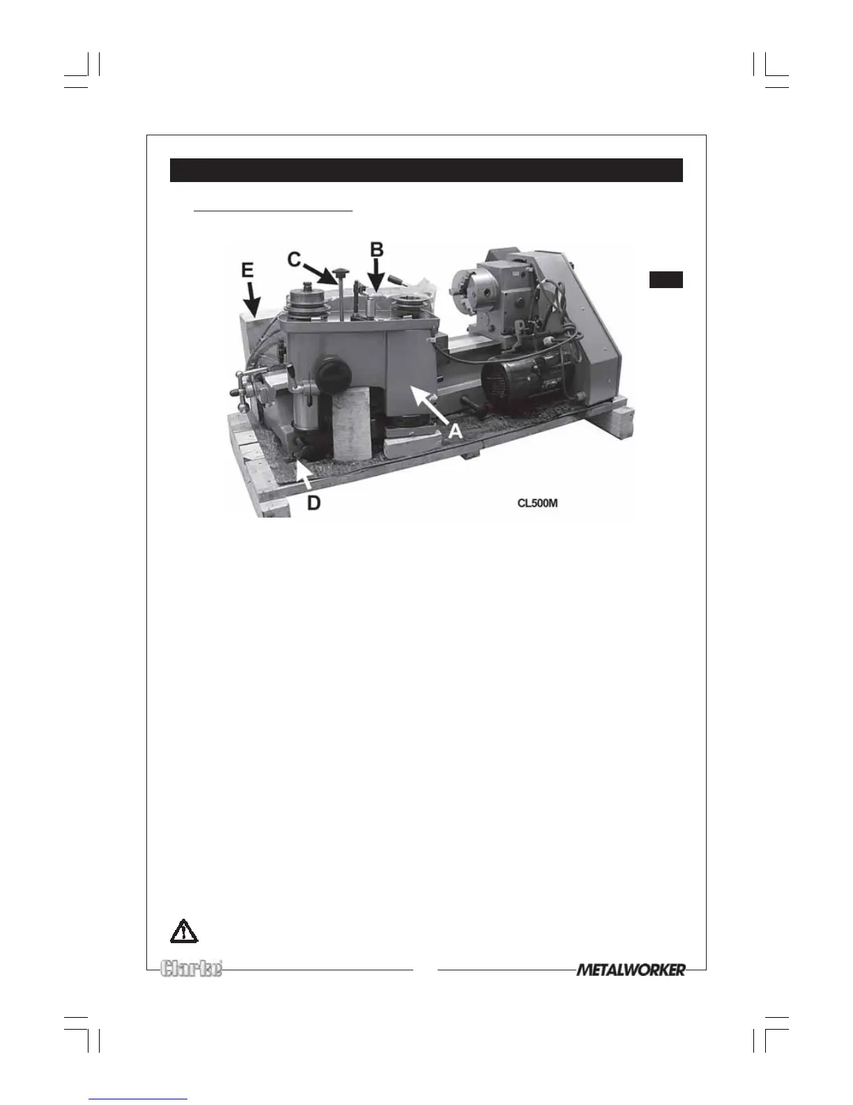
Fig.1
UNPACKING & INSTALLATION
Mounting the Lathe
On receipt, carefully remove the wooden casing to expose the lathe.
Fig.1, shows model CL500M. Model CL430 is similar, but does not include the Mill Head
- shown at ‘A’. CL430 users should therefore ignore all reference to the Mill Head .
Inspect to ensure that no damage was suffered during transit. Should any damage
be apparent, please contact your Clarke dealer immediately.
• Carefully remove the Mill Head Pulley Cover ‘B’.
• The Mill Head is shown at A, and is secured with a rod - C. Undo the nut, on the
threaded rod, and remove completely so that the mill head can be lifted free.
Place it carefully to one side, noting that it is connected to the lathe by an
electric cable. Take great care not to damage the bevel gears within the head.
• Remove the wooden box - E, which contains loose parts, as described below.
• Undo the nuts securing the two straps, one of which is shown at D, the other on
the diagonally opposite lifting handle, and remove the straps completely.
The lathe is now free to be lifted.
NOTE: For ease of installation, you may prefer to free the mill head by disconnecting
the cable attached to the mill head microswitch, slackening off the cable clamps
and withdrawing the cable completely.
Ensure you take note of the positioning of the spade connectors on the microswitch
before you disconnect.
• Four retractable handles are provided to ease manoeuvrability, but it is strongly
recommended that a sling be used, on the handles, to raise the lathe with a suitable
hoist in order to be located on a strong sturdy workbench or optional Floor Stand.
CAUTION The weight (129kg - 285lbs) is concentrated at the headstock end
- take the necessary precautions when lifting.