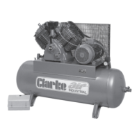
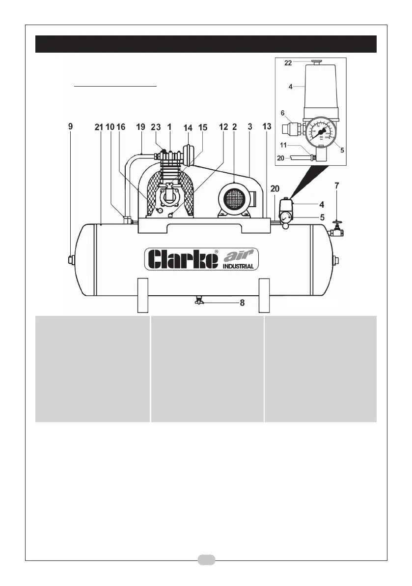
GENERAL ARRANGEMENT
1. Air Compressor Pump 8. Drain Tap 16. Oil Level Sight Glass
2. Electric Motor 9. Inspection Plug 17. –
(or petrol/diesel engine) 10. Non-Return Valve 18. –
3. Wire Guard 11. Air Bleed Valve 19. Air Delivery Pipe
4. Pressure Switch 12. Oil Drain Plug 20. Air Bleed Pipe
5. Pressure Gauge 13. Saddle 21. Air Receiver
6. Safety Valve 14. Air Intake Filter 22. On/Off switch
7. Ball Valve 15. Oil Filler/Breather 23. Auto Air Bleed
NOTES:
1. On automatic machines 10 H.P. & above a solenoid valve is fitted to the
delivery pipe.
2. On automatic machines 10 H.P. & above, an Auto Star Delta (ASD) starter is
fitted, ready to be mounted to a wall or panel etc. It is IMPORTANT to note
that NO ADJUSTMENTS should be made to this component.
The ASD should be connected to a 3-phase supply by a qualified electrician.
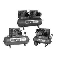
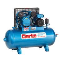
A. STATIONARY
NB: Must be mounted on anti-vibration pads.
Fig.2
7
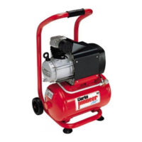
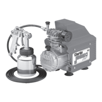
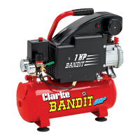
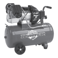
Illustrative
purposes only
 Loading...