4
English
S E T
C /F
-
A A 1 . 5V
+
-
A A 1 . 5V
+
7 8 9
10
11
12
1
2
1
S E T
C / F
-
A A 1 . 5V
+
-
A A 1 . 5V
+
1
1
1
%
1
1
1
S E T
C / F
-
A A 1. 5 V
+
-
A A 1. 5 V
+
1
1
1
%
1
1
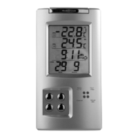
WS2015 receiver
WT450 transmitter
20
21
13
14
15
16
17
18
19
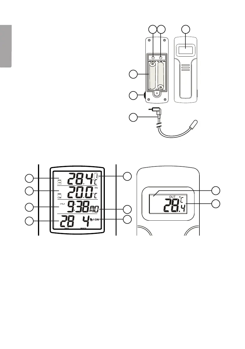
Transmitter (sensor)
7. [SET]: Channel and house code
setting button. Pushto select
achannel for thesensor and to set
acode to suit your receiver unit.
Thiscould be important if there is
other radio equipment close by
which might interfere.
8. [C/F]: Changes between Celsius
and Fahrenheit and also between
channels and house codes.
9. LCD display.
10. Batterycompartment.
11. Connectingan external
temperature sensor.
12. Externaltemperature sensor.
Displays
13. Outdoortemperature and trend
14. Indoortemperature and trend
15. Clock/Alarm clock
16. Date/Month
17. Channel
18. Day
19. Alarmclock symbols
20. Channel
21. Outdoortemperature
Batteries
• Insert thebatteries into thereceiver first, then the transmitter (sensor).
• When inserting thebatteries, place thetransmitter and thereceiver unit close to
each other to make sure that they synchronise.
• Position thetransmitter and receiver within operating range of one another.