11
Section 1 - Furnace Installation
NOTE: All holes made in basement or building
walls must be sealed completely to prevent water
from entering the building.
4. Close all valves on the outdoor furnace.
5. Install ttings to allow pressure-testing of both
supply and return lines. Pressurize with 50 psi (3.5
kg/cm
2
) of air; then check after 30 minutes to see if
pressure has dropped. A drop in pressure indicates a
leak; repair as necessary.
6. Connect the supply and return lines to the outdoor
furnace and the existing heat emitter(s). Fig. 7 shows
some of the PEX ttings and tools used in making
connections.
Fig. 7
CAUTION
Allow for expansion and contraction of the
supply and return lines at each end. Without
an allowance for expansion and contraction,
the lines may kink or the ttings may be pulled
apart, causing an immediate water loss from the
outdoor furnace. Central PEX water lines can
have an expansion and contraction rate up to
.095" per each 100 ft and each 10°F (2.4 mm/30
m/5.5˚C).
7. Make sure there are no leaks in the supply and return
lines; then backll the trench.
NOTE: Do not backll the trench until the supply
and return lines have been tested to ensure there
are no leaks.
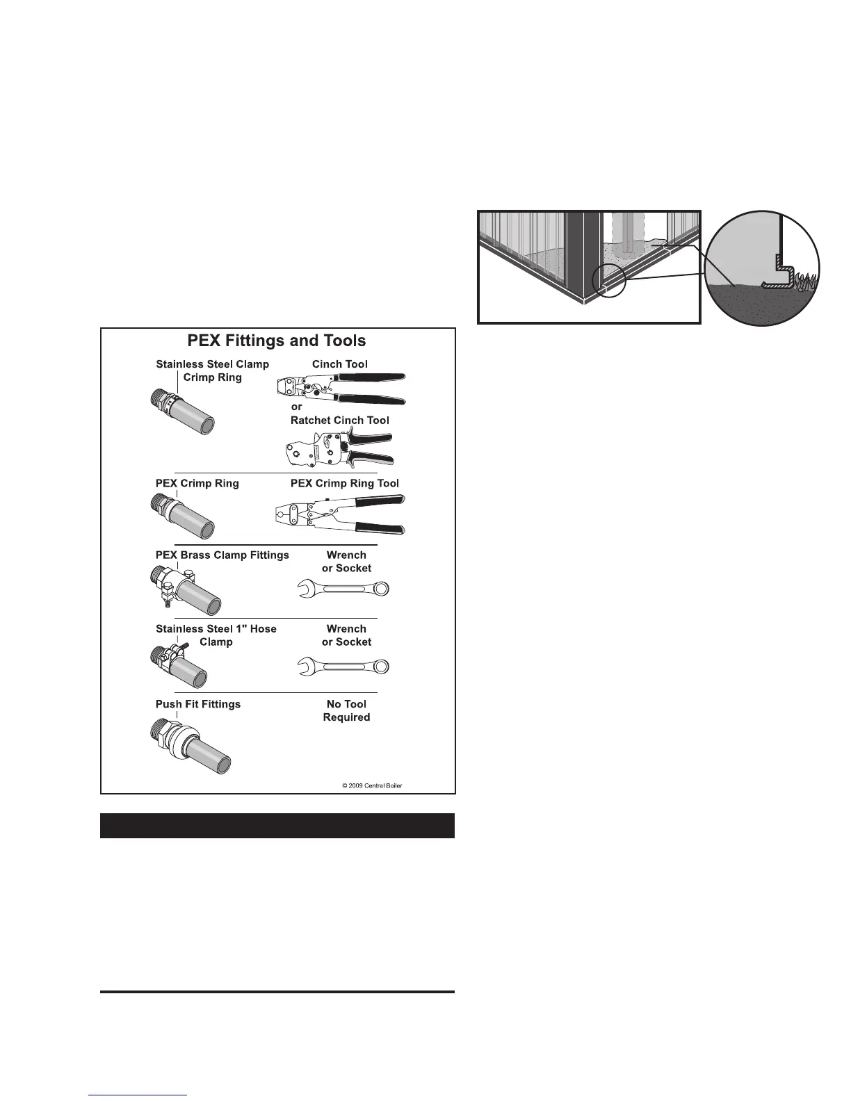
8. Install the base trim; then, using gravel or small
rock, backll the perimeter of the ThermoPEX line
enclosure to the bottom, inner edge of the base (Fig.
8). Install the siding panel.
Fig. 8
Gravel or
Small Rock
CIRCULATION PUMPS
NOTE: The direction of water ow is very
important for the proper operation of the outdoor
furnace. Installing a swing check valve in the
return line can prevent possible reverse ow.
Water Flow
For a single building water-to-air heat exchanger system
with a domestic water heater, the direction of water
ow must go from the hot outlet on the outdoor furnace
to the lower side tting of the domestic water heater
exchanger, to the lower tting of the heat exchanger
in the plenum of the existing furnace, and then to the
return port of the outdoor furnace.
NOTE: Some systems may have different ow
patterns.
Access to Ports on Outdoor Furnace
The upper ports are the hot supply outlets and the lower
ports are the return inlets. This conguration allows for
mounting the circulation pumps on the outdoor furnace.
Fig. 9 through Fig. 13 show different congurations for
proper supply and return line and pump installations.
The Taco 009 is a medium ow, high head pressure
pump that requires an adequate amount of pressure on
the outlet side to prevent the motor from overloading.
The Taco 014 is a high ow, high head pressure pump
that requires an adequate amount of head pressure on
the inlet side to prevent cavitation. Therefore, a Taco
014 may need to be mounted lower near the base of the
furnace, and on the 1-1/4" bung.
The Taco 007 is a medium to high ow, low head
pressure pump. In a very low-resistance system (e.g.,
short length of supply and return lines, only a at
plate heat exchanger, etc.), the 007 pump may need to
be mounted lower near the base of the furnace or on
the 1-1/4" bung to prevent cavitation at high water
temperatures.
NOTE: See the Hydronic Component Selection
Guide (p/n 2482) for more information.
 Loading...