User Guide| KB-702/KB-702GM/KB-802-GM-IM
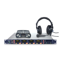
Two Channel
Cable Wiring
KB-702 Intercom
Connector
XLR
Connectors
Channel A
Channel B
Pin 1
Pin 5
1
3
2
1
3
2
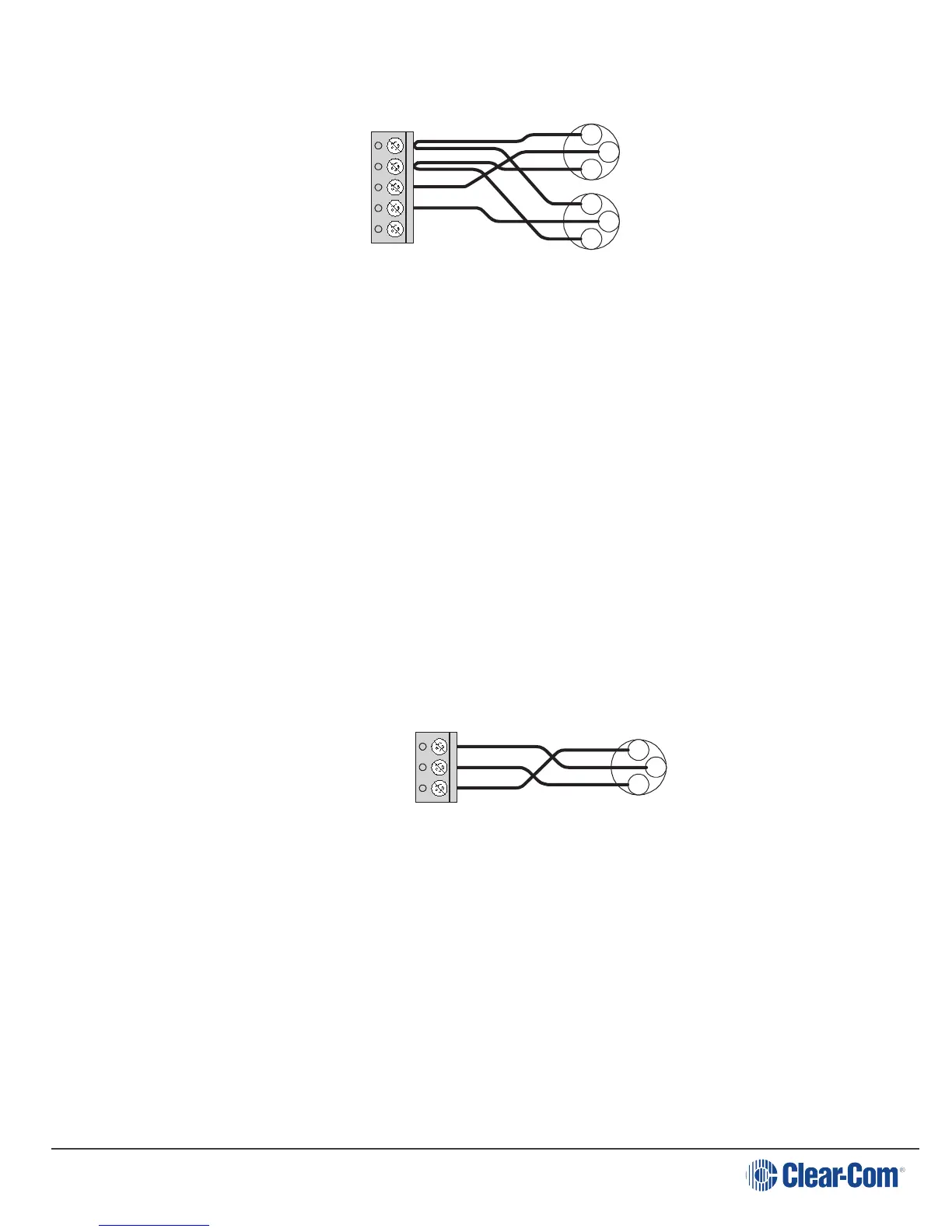
5. Program Input: A 3-terminal plug-on connector provides the program input to
the station. Program is fed to the headset and speaker. The level to the speaker
or headset is controlled by the program level control. The program input accepts
a balanced or unbalanced line-level audio signal. If this input is connected to the
stage announce (SA) output of a main station it can be used as a paging input.
Since the level of this input is independently adjustable from the intercom audio
volume, it can be used to override the intercom audio.
The pinout of the program input connector is as follows:
Pin 1 --- Ground (shield)
Pin 2 --- + Signal
Pin 3 --- - Signal
Program Input
Cable Wiring
KB-702 Program
Input Connector
XLR
Connector
Pin 1
1
3
2
Pin 3
6. Option Board Jumpers:The three jumper plugs P1, P2, and P3 must be installed
when optional modules are not used. When the optional EB7-4W four-wire
module is used, both P1 and P3 must be removed. In the KB-702GM/KB-802GM-
IM, P2 is replaced by the VOX module. Save these jumper plugs for possible
future use after removing them. The KB-702 will not operate without
either these jumper plugs or the optional modules installed.
Page 17