User Guide| KB-702/KB-702GM/KB-802-GM-IM
3. Call Signal Jumper: In some installations it is important to receive a call
signal from either channel, regardless of the setting of the channel selector. The
plug-on jumper P1 makes the call light respond to either (a) the selected
channel or to (b)either channel, depending upon its orientation. By default, the
jumper is set to the selected channel position. When the TW or 4-Wire Option
modules are installed, this jumper is not used. In TW operation, the call signal
always originates on channel A. In 4-Wire operation, the call signal is not used.
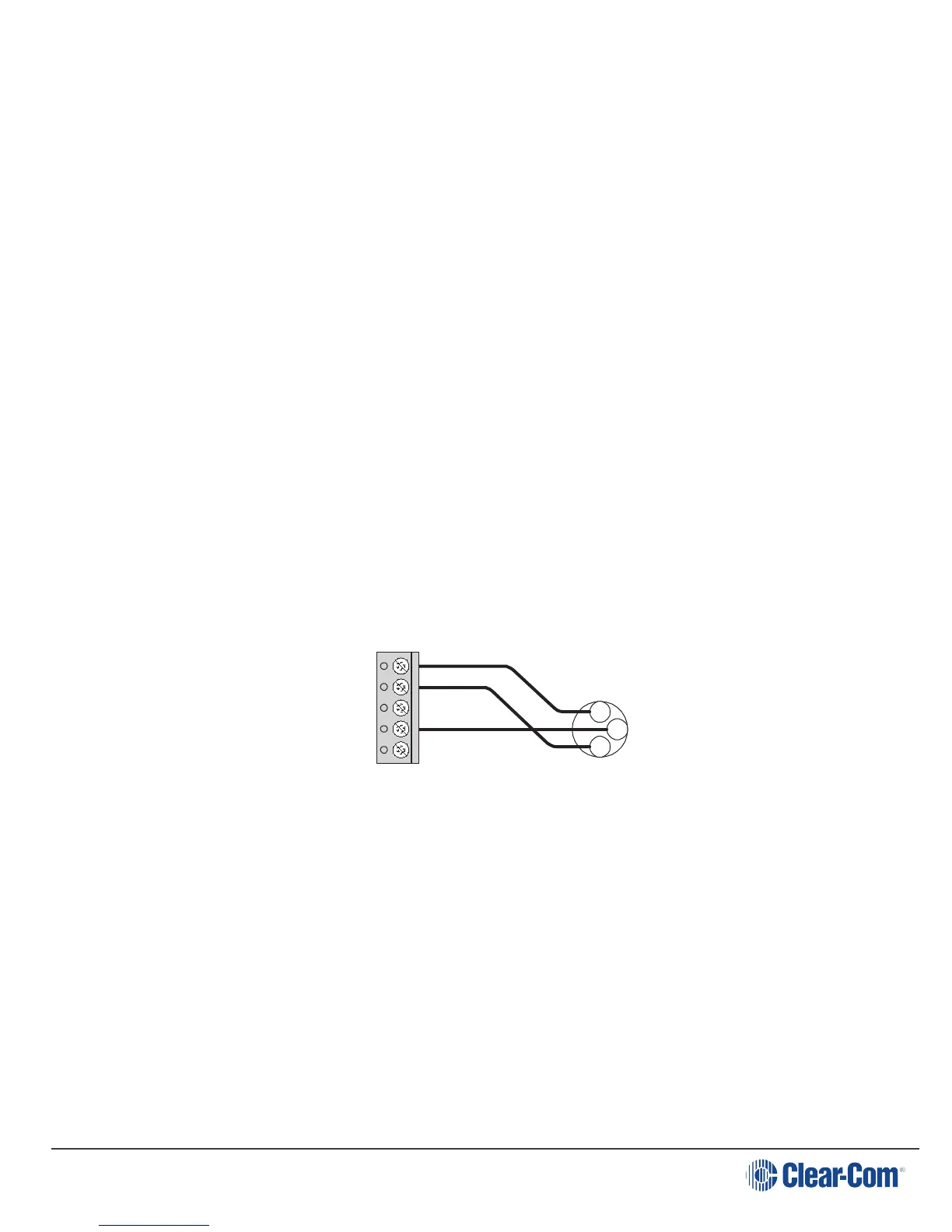
4. Intercom Line Connection: The KB-702 contains a 5-terminal plug-on
connector for intercom line connection. This connector is intended to be
unplugged from the circuit board when connecting the intercom line, and then
plugged back on when the wiring is completed. The connections for each pin are
visible on the circuit board when the connector is unplugged. The pinout of this
connector is as follows:
Pin 1 --- (NC)
Pin 2 --- Channel A Audio
Pin 3 --- Channel B Audio
Pin 4 --- Power
Pin 5 --- Ground (Shield)
One Channel
Cable Wiring:
KB-702 Intercom
Connector
XLR
Connector
Channel A
Pin 1
Pin 5
1
3
2
Page 16