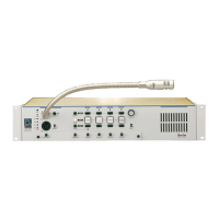
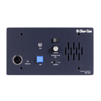
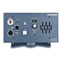
SB-704 MAIN STATION
2-9
Pin 2 --- - Signal
Pin 3 --- + Signal
The signal level is 0 dBu and transformer isolated.
IFB/HOT MIC (REAR PANEL, 1/4-INCH
PHONE JACK)
A ¼ in. (0.64 cm) phone jack marked IFB/hot Mic provides an output signal
from the selected microphone. This output is also intended to work with
Clear-Com’s IFB system. Consult the factory for installation instructions.
The jack connections are as follows:
Tip --- Hot mic output
Ring --- Control signal in
Sleeve --- Ground
EXTERNAL SPEAKER (REAR PANEL,
1/4-INCH PHONE JACK)
A ¼ in. (0.64 cm) phone jack marked external speaker provides the power
amplifier output of the station intended for driving an external speaker. The
jack connections are as follows:
Tip --- Speaker amplifier output
Ring --- No connection
Sleeve --- Ground
ACCESSORY (REAR PANEL, DB-15F)
The accessory DB-15F connector on the rear panel provides auxiliary
program inputs for each channel, remote mic on/off input, line level output,
and announce relay contacts. The pin assignments of the connector are as
follows:
 Loading...
