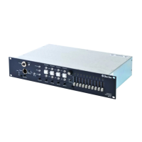
SB-704 MAIN STATION
2-5
Portable Installation Cable
Practical cable for portable system interconnections is flexible,
two-conductor, shielded microphone cable. We suggest you use Belden
#1800F (24 gauge). For runs longer than 500 ft. (152.5 m) use a 20 gauge
cable or larger (Belden #8412).
Permanent Installation Cable
Vinyl-jacketed shielded pair is the cable of choice for permanent installations.
Use a low-capacitance 20 gauge wire for runs under 500 ft. (152.5 m). We
suggest you use Belden #8762. For runs longer than 500 ft. (152.5 m) use an
18 gauge cable (Belden #8760). Placing the cable in conduit is recommended
but not necessary.
Multi-pair cable that is individually shielded is acceptable for use in
multi-channel systems. For cross-talk considerations, the shields must be tied
together on both ends of the cable to produce the lowest possible DC path for
ground return.
WIRING DIAGRAM
The diagram shows using a multi-pair cable to connect two stations. Note that
the power and shield wires of each channel are not connected together.
GROUND ISOLATION
The pin #1 ground connection of each XLR connector must also be isolated
from the chassis. Pin #1 should not be connected to the shell of the XLR
connector.