Section 2 — Installation
Part No. 750-263 2-3
A. ASSEMBLY
1. Packaging
The Cleaver-Brooks Model CFC boiler is shipped in three parcels.
The pressure vessel assembly mounted on a skidded crate, the
control panel in a box, and the outer casing with insulation in a
skidded box. It is recommended that the pressure vessel be properly
mounted with all piping connections attached prior to installation of
the casing.
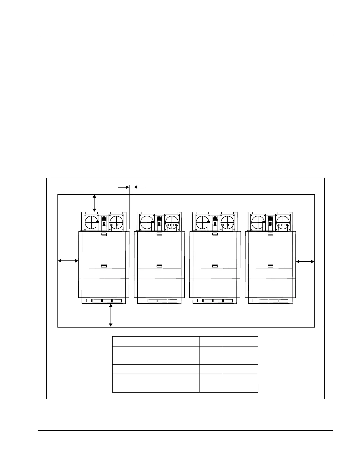
2. Boiler placement
The boiler or boilers should be mounted in a space in accordance
with Figure 2-1 below. Required front, rear, and side clearances are
shown.
Note: If the boiler room is constructed with non-combustible
walls, it is possible to install the units closer to the side
walls, but the front and rear clearances must be
maintained.
S
Figure 2-1 Clearance Required
DIM Inches
Top Clearance A 14
Side Clearance B 20
Backway C 20
Front D 36
Between Boilers E 3
C
B
D
B
E