Profire V Burner Chapter 2
750-177 2-13
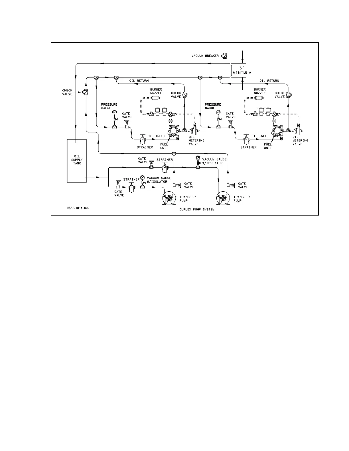
Figure 2-12: Typical Flooded Loop System
GAS PIPING
Refer to Figures 2-5 through 2-6 for typical gas piping arrangements.
Normally, the control train is ordered to
suit a particular code or insurance regulation, such as UL/cUL, FM, or GAP. Gas service and house piping must
supply the quantity of gas demanded by the unit at the pressure required at the burner gas train inlet.
All piping must be in strict accordance with applicable codes, ordinances, and re
gulations of the supplying
utility. In the absence of other codes, piping should be in accordance with National Fuel Gas Code, NFPA No.
54, ANSI No. Z223-1.
Gas train components upstream of the butterfly valve
are shipped loose. These components should be
mounted by the installer as close to the butterfly valve as practical. If a pre-piped and wired gas train is
ordered, the components upstream of the first safety shutoff valve are shipped loose. These components
should also be mounted by the installer.
Arrange gas piping at the burner so that
the burner is accessible for servicing without disassembly.The pilot
gas train is supplied with the burner, and is factory installed. The gas pilot supply line must be connected
upstream of the main gas regulator. If a reducing bushing is required between the house piping and the burner
piping, it should be close to the burner shutoff valve.
The gas piping must be internally clean and free of foreign
material. Before using in service, a leak test must
be performed.

 Loading...


