10 P2349HW | 2019-08 Apex Tool Group
1
EN
5 Pin Assignment
This chapter describes the Cleco Production Tools specific
connectors. Standard plugs are not considered. All connec-
tions are short-circuit proof.
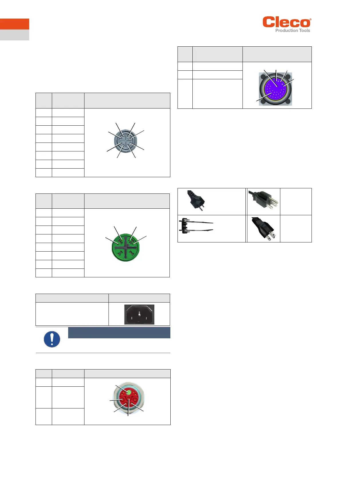
X21 – TSnet System Bus Out
Interface port for TSnet cable.
X22 – TSnet System Bus In
X23 – Supply
X24 – Tool Cable 30/50E×N… Series
X25 – Tool Cable 18/48E×E… Series
6 Items Delivered
Check delivery for transit damage and ensure that all items
have been supplied:
• Controller
• EC Declaration of Conformity
• Hardware Description
• SP-1500
• Warranty
• Mating Connector
Pin Signal 8 Pin M12 Circular Connector
X-Coded
1 Tx +
2 Tx -
3 Rx +
4 RX -
5 0 VDC
6 0 VDC
7 +24 VDC
8 +24 VDC
Pin Signal 8 Pin M12 Circular Connector
X-Coded
1 Tx +
2 Tx -
3 Rx +
4 RX -
5 0 VDC
6 0 VDC
7 +24 VDC
8 +24 VDC
Description IEC Connector C14
Connector with Fuse Holder
2-Pin, 5 × 20 mm, 16 A
Slow-Blow
Note
Use plug locking mechanism.
See Quick Installation Guide.
Pin Signal M23 circular connector
1-3 Power
4 PE
(functional
ground)
5 Tool bus
2
1
8
7
6
5
4
3
1
2
3
4
1
2
3
4
5
Pin Signal ECTA Circular Connector
Push-Pull
1-3 Power
4PE
5 Signals
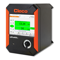
Power Cable
EU 230 VAC
Order no.
541683-03
Power Cable
USA 115 VAC
Order no.
541683-01
Plug Locking
Mechanism
Order no.
544004-1
Power Cable
USA 230 VAC
Order no.
541683-02
5
1
2
3
4