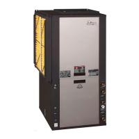
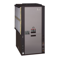
EasyManua.ls Logo

ClimateMaster Tranquility TTV064 Series User Manual

ClimateMaster Tranquility TTV064 Series
56 pages
To Next Page IconTo Next Page
Page #1 background imageLoading...
Page #1 background image
Tranquility
®
30
(TT) Series
Models TTD/H/V 026 - 072
60 Hz - HFC-410A
INSTALLATION, OPERATION,
& MAINTENANCE
97B0075N05
Revised: 18 July, 2013
Table of Contents
Model Nomenclature 3
Unit Physical Data 6
Horizontal Installation 7
Field Conversion of Air Discharge 9
Horizontal Installation 10
Vertical Installation 11
Piping Installation 13
Water-Loop Heat Pump Applications 14
Ground-Loop Heat Pump Applications 15
Ground-Water Heat Pump Applications 17
Water Quality Standards 19
Electrical - Line Voltage 20
Electrical - Power Wiring 22
Electrical - Power & Low Voltage Wiring 23
Electrical - Low Voltage Wiring 24
Electrical - Thermostat Wiring 26
Blower Performance Data 27
ECM Blower Control 28
Typical Wiring Diagram - Units with CXM Board
and ECM Fan Motor (Single Phase) 30
Typical Wiring Diagram - Units with
ClimaDry
®
(Single Phase) 31
Typical Wiring Diagram - Units with CXM Board, 32
ECM Fan Motor, and MPC (DDC) CONTROLS
(SINGLE PHASE) 32
CXM Controls 33
DXM Controls 34
Safety Features - CXM and DXM Controls 36
ClimaDry
®
Modulating Reheat Option 38
Unit Starting and Operating Conditions 41
Piping System Cleaning and Flushing 42
Unit and System Checkout 44
Unit Start-Up Procedure 45
ClimaDry
®
II Option Corrections
(When Operating in Non-ClimaDry
®
Mode) 46
Unit Operating Conditions 47
Preventive Maintenance 49
Functional Troubleshooting 50
Performance Troubleshooting 51
Start-Up Log Sheet 52
Functional Troubleshooting 53
Warranty (U.S. & Canada) 54
Warranty (International) 55
Revision History 56

Questions and Answers:

ClimateMaster Tranquility TTV064 Series Specifications

General IconGeneral
CategoryHeat Pump
RefrigerantR-410A
Phase3
Compressor TypeScroll
ModelTTV064
TypeWater Source
Voltage208/230V

Summary

Model Nomenclature

General Information

Safety

Details critical safety warnings and precautions for installation and operation.

Horizontal Installation

Vertical Installation

Piping Installation

Supply and Return Piping Guidelines

General guidelines for installing supply and return piping, including valves and hose kits.

Water-Loop Heat Pump Applications

Ground-Loop Heat Pump Applications

Ground-Water Heat Pump Applications

Electrical - Line Voltage

Line Voltage Wiring and Transformer

Ensuring correct voltage match and instructions for transformer wiring.

Electrical - Power Wiring

Power Connection and Transformer Wiring

How to make power connections and instructions for transformer wiring.

Electrical - Power & Low Voltage Wiring

Electrical - Low Voltage Wiring

Thermostat and Solenoid Valve Wiring

How to wire thermostats and guidelines for water solenoid valves.

Electrical - Thermostat Wiring

Thermostat Installation and Wiring Diagrams

Proper thermostat placement, mounting, and illustrative wiring diagrams.

ECM Blower Control

Typical Wiring Diagram - CXM Board, ECM Fan Motor (Single Phase)

Typical Wiring Diagram - Units with ClimaDry® (Single Phase)

Typical Wiring Diagram - CXM, ECM, MPC (DDC) CONTROLS (SINGLE PHASE)

CXM Controls

DXM Controls

Safety Features - CXM and DXM Controls

Fault Handling and Lockout Modes

Explains control behavior during faults, including retry attempts and lockout conditions.

ClimaDry® Modulating Reheat Option

UNIT STARTING AND OPERATING CONDITIONS

Unit Starting and Operating Conditions

Piping System Cleaning and Flushing

Flushing/Purging Units with ClimaDry®

Unit and System Checkout

Unit and System Checkout Procedures

Essential checks for unit components, wiring, fan, controls, and system water before powering up.

Unit Start-up Procedure

Cooling and Heating Cycle Analysis

Steps for analyzing unit performance during cooling and heating cycles using temperature and pressure data.

Preventive Maintenance

Functional Troubleshooting

Fault Code and Unit Specific Troubleshooting

Lists common faults, causes, solutions, and troubleshooting steps for unit operational issues.

Heating and Cooling Cycle Analysis

Diagrams and formulas for analyzing heating and cooling cycle performance.

Performance Troubleshooting

Capacity, Pressure, and Temperature Issues

Diagnosing and resolving issues with insufficient capacity, head pressure, suction pressure, and air temperatures.

Related product manuals