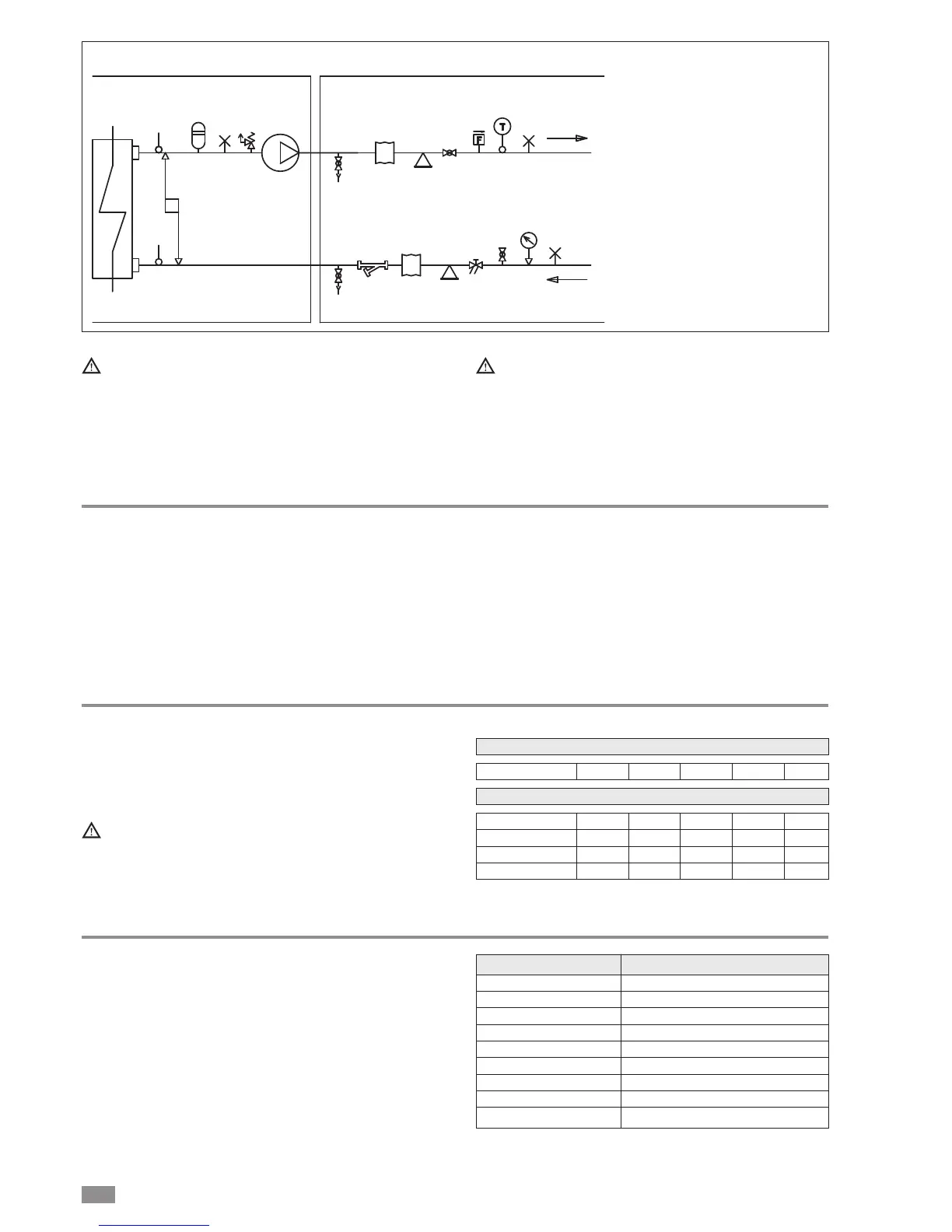
System water circuit connection diagram, BRN2 version WITH HYDRONIC KIT
1 PRESSURE GAUGE
2 VIBRATION-ISOLATING JOINT
3 SHUT-OFF VALVE
4 CALIBRATING VALVE
5 FLOW SWITCH
6 THERMOMETER
7 CIRCULATOR PUMP
8 SAFETY VALVE
9 EXPANSION VESSEL
10 MESH FILTER
11 FILL/TOP-UP
12 TEMPERATURE PROBE
13 DIFFERENTIAL PRESSURE
SWITCH
14 DRAIN/CHEMICAL WASHING
VALVE
15 SYSTEM VENT
Must be provided with a filling/top-up system connected
to the return line and a drain cock in the lowest part of
the installation.
Installations containing antifreeze or covered by spe-
cific legislation must be fitted with water circuit discon-
nectors.
The manufacturer is not liable for obstruction, breakage
or noise resulting from the failure to install filters or
vibration dampers.
Particular types of water used for filling or topping up
must be treated with appropriate treatment systems.
For reference values, see the table.
Risk of freezing
The unit must be prevented from freezing at outside air tem-
peratures around 0°C.
The following are recommended:
• use suitable percentages of antifreeze (see “Ethylene gly-
col solutions”)
• protect the piping with heating sheaths,
• empty the system, making sure no water remains at the
lowest points in the circuit or there are closed valves
where water may stagnate.
It is recommended to use non-toxic food grade antifreeze,
compliant with the standards in force in the countries where
the unit is used, if domestic hot water production is also fea-
tured.
The antifreeze used must be corrosion inhibited and com-
patible with the water circuit components.
Ethylene glycol solutions
Water and ethylene glycol solutions used as a heat carrier in
the place of water reduce the performance of the unit.
Multiply the performance figures by the values given in the
following table.
The heat pumps must be fitted with a filling/top-up sys-
tem connected to the return line and a drain valve in the
lowest part of the system.
Systems containing antifreeze or covered by specific
legislation must be fitted with low-loss headers.
cPf
cQ
cdp
0
1
1
1
12%
0,985
1,02
1,07
20%
0,98
1,04
1,11
28%
0,974
1,075
1,18
35%
0,97
1,11
1,22
40%
0,965
1,14
1,24
0 -5 -10 -15 -20 -25
Freezing point (°C)
Percentage of ethylene glycol by weight
cPf: cooling capacity correction factor
cQ: flow rate correction factor
cdp: pressure drop correction factor
Water quality
The water used in the system and domestic hot water cir-
cuits must comply with the following characteristics:
PH 6-8
Electrical conductivity less than 200 mV/cm (25°C)
Chlorine ions less than 50 ppm
Sulphuric acid ions less than 50 ppm
Total iron less than 0.3 ppm
Alkalinity M less than 50 ppm
Total hardness less than 50 ppm
Sulphur ions none
Ammonia ions none
Silicon ions less than 30 ppm