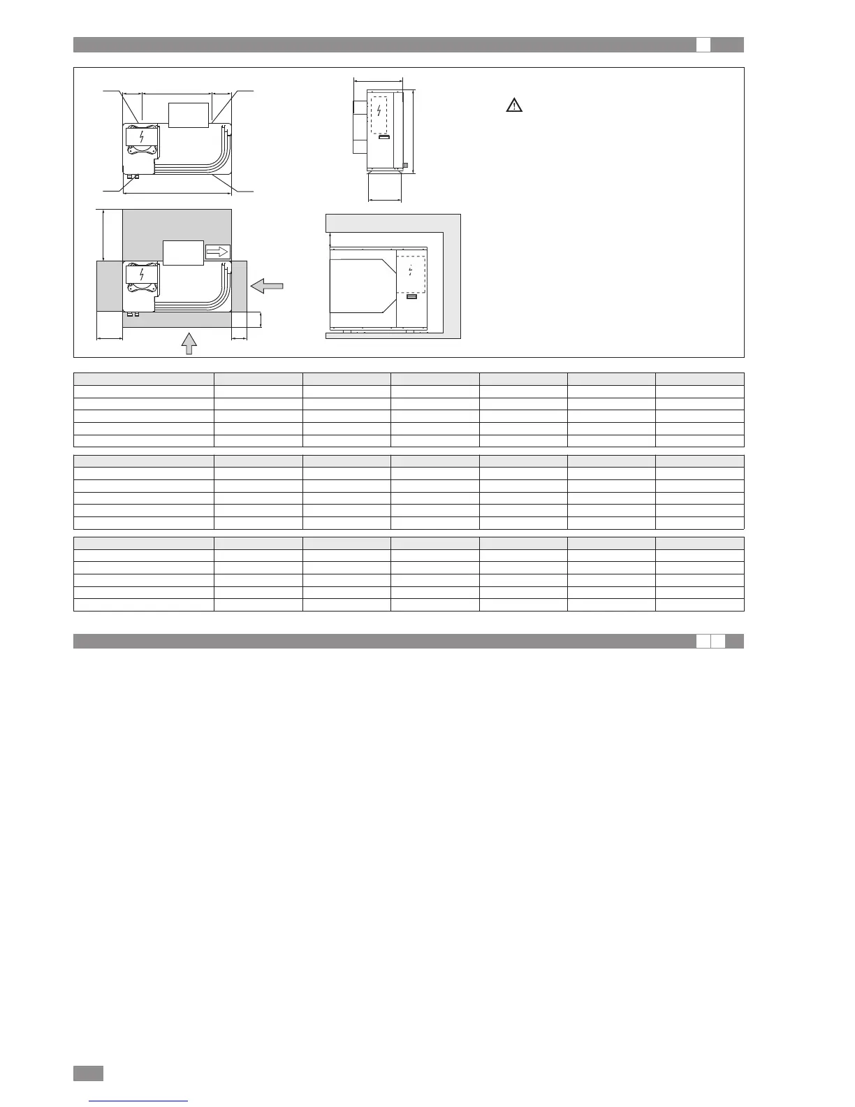
* For installation with open outlet, the
minimum distance is increased from
400mm to 1500mm
BRA2 - BRN2 EN
6
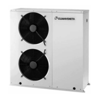
DISEGNI DIMENSIONALI
I
HYDRAULIC CONNECTIONS
I A
The choice and installation of components is the responsibil-
ity of the installer who should follow good working practice
and current legislation. Before connecting the pipes, make
sure they do not contain stones, sand, rust, dross or other
foreign bodies which might damage the unit. Construction of
a bypass is recommended to enable the pipes to be washed
through without having to disconnect the unit (see drain
valves). The connection piping should be supported in such
a way as to avoid it weighing on the unit. It is recommended
that the following devices are installed in the water circuit of
the evaporator:
1. Two pressure gauges with a suitable scale (inlet and outlet).
2. Two vibration damper joints (inlet and outlet).
3. Two gate valves (normal in inlet and calibrating in outlet).
4. A flow switch on the unit outlet to the system circuit (com-
pulsory). The flow switch must be calibrated by the
installer to a value equal to 70% of rated flow.
5. Due termometri (in ingresso e in uscita).
6. An intake filter must be installed as close as possible to
the evaporator and positioned to allow easy access for
routine maintenance. 500 micron filter
7. All the pipes must be insulated with suitable material to pre-
vent the formation of condensate and heat loss. The insu-
lating material must be a vapour barrier. Make sure that the
control and shut-off devices protrude from the insulation.
8. At the lowest points in the system, install drain valves for
easy emptying.
9. At the highest points in the system, install automatic or
manual air vent valves.
Failure to install the flow switch will mean the heat exchang-
er is not protected in the event of no flow of liquid.
Climaveneta cannot be held liable for any damage to the
unit and/or the system following the failure to install these
devices or the filter.
The correct operation of the components that help ensure
the safety of the appliance and the system should be
checked regularly.
Specifically, this involves cleaning the filters and checking
the operation of the flow switches installed.
Water flow to the chiller unit must conform to the values
shown in the section on “General Technical Data”.
The flow of water must be maintained constant during oper-
ation.
The water content of the unit must be such as to avoid dis-
turbing operation of the refrigerant circuits.
Dimension 0021M-T 0025M-T 0031M-T 0041M-T 0051T 0061T
A 900 900 900 900 900 900
B 640 940 940 1240 1240 1390
C 580 580 580 580 580 630
D 320 320 320 320 320 370
E 580 580 580 580 580 580
Weight Distribution BRA2 0021M-T 0025M-T 0031M-T 0041M-T 0051T 0061T
W1 30 35 36 48 54 57
W2 11 12 13 17 19 20
W3 23 26 27 36 40 42
W4 41 47 49 64 72 76
TOT 105 120 125 165 185 195
Weight Distribution BRN2 0021M-T 0025M-T 0031M-T 0041M-T 0051T 0061T
W1 33 38 39 52 58 61
W2 12 13 14 18 20 21
W3 25 28 30 40 44 46
W4 45 51 53 70 78 82
TOT 115 130 135 180 200 210