BRA2 - BRN2 EN
13
ELECTRICAL CONNECTIONS
I A
The BRA2 and BRN2 units leave the factory already wired,
and require the installation of an omnipolar thermal overload
switch, a lockable mains disconnecting switch for the con-
nection to the mains power supply, and the connection of
the flow switch to the corresponding terminals. All the above
operations must be carried out by qualified personnel
in compliance with the legislation in force.
For all electrical work, refer to the electrical wiring diagrams
in this manual.You are also recommended to check:
- that the characteristics of the mains electricity supply are
adequate for the absorptions indicated in the electrical
characteristics table below, also bearing in mind
Power to the unit must be turned on only after installa-
tion work (hydraulic and electrical) has been completed.
All electrical connections must be carried out by quali-
fied personnel in accordance with legislation in force in
the country concerned.
Respect instructions for connecting phase, neutral and
earth conductors.
The power line should be fitted upstream with a suitable
device to protect against short-circuits and leakage to
earth, isolating the installation from other equipment.
Voltage must be within a tolerance of ±10% of the rated
power supply voltage for the unit (for three phase units,
the unbalance between the phases must not exceed
2%). If these parameters are not respected, contact the
electricity supply company.
For electrical connections, use double insulation cable
in conformity with current legislation in the country con-
cerned.
An omnipolar thermal overload switch and a lockable mains
disconnecting switch, in compliance with the CEI-EN stan-
dards (contact opening of at least 3mm), with adequate
switching and residual current protection capacity based on
the electrical data table shown below,must be installed as
near as possible to the appliance.
The devices on the unit must be lockable.
An efficient earth connection is obligatory. Failure to
earth the appliance absolves the manufacturer of all lia-
bility for damage.
In the case of three phase units, ensure the phases
are connected correctly.
Do not use water pipes to earth the unit.
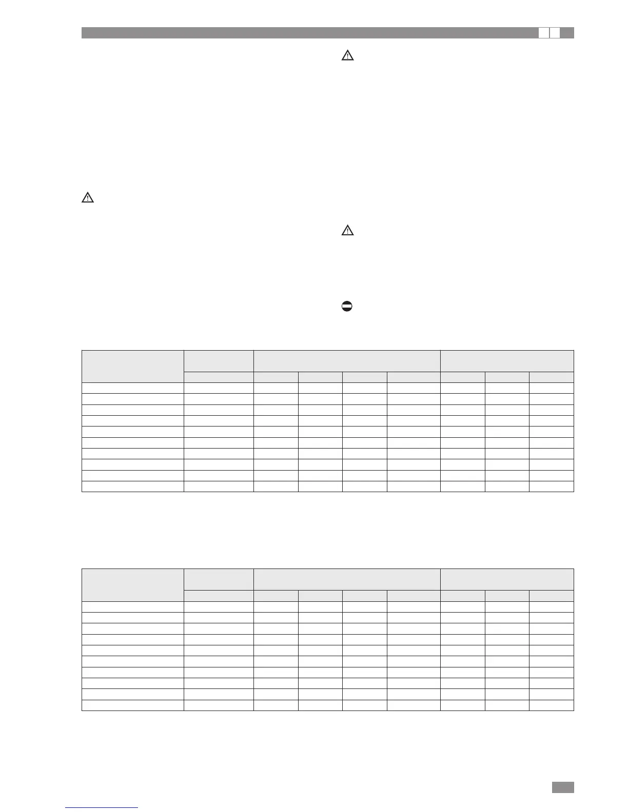
ELECTRICAL DATA, BRA2 AND BRN2 WITHOUT HYDRONIC KIT
F.L.I. Maximum power input
F.L.A. Maximum current input
S.A. Start-up current
S.A. LIM Peak current with peak limiter
Maximum values for sizing the protection switches and power supply cables
Size
Power supply Maximum values Fuses (5x20T 250V)
(V-Ph-Hz) FLA [A] FLI [kW] SA [A] SA LIM [A] FU1 FU2 FU3
BRA2 - BRN2 0021 230-1N-50 18,4 3,42 63,4 29,4 4A 3,15A 2A
BRA2 - BRN2 0025 230-1N-50 21,4 4,19 84,4 39,4 4A 3,15A 2A
BRA2 - BRN2 0031 230-1N-50 25,4 5,09 99,4 46,4 4A 3,15A 2A
BRA2 - BRN2 0041 230-1N-50 29,4 6,34 134,7 49,7 4A 6,3A 2A
BRA2 - BRN2 0021 400-3N-50 7,9 3,42 34,4 20,4 4A 3,15A 2A
BRA2 - BRN2 0025 400-3N-50 8,4 3,95 37,4 21,4 4A 3,15A 2A
BRA2 - BRN2 0031 400-3N-50 10,4 4,76 50,4 28,4 4A 3,15A 2A
BRA2 - BRN2 0041 400-3N-50 12,4 6,36 68,7 39,7 4A 6,3A 2A
BRA2 - BRN2 0051 400-3N-50 14,2 6,42 68,7 39,7 4A 6,3A 2A
BRA2 - BRN2 0061 400-3N-50 17,4 7,75 78,7 45,7 4A 6,3A 2A
ELECTRICAL DATA, BRA2 AND BRN2 WITH HYDRONIC KIT
F.L.I. Maximum power input
F.L.A. Maximum current input
S.A. Start-up current
S.A. LIM Peak current with peak limiter
Maximum values for sizing the protection switches and power supply cables
Size
Power supply Maximum values Fuses (5x20T 250V)
(V-Ph-Hz) FLA [A] FLI [kW] SA [A] SA LIM [A] FU1 FU2 FU3
BRA2 - BRN2 0021 230-1N-50 19,0 3,50 64,0 30,0 1,25A 1,25A 2A
BRA2 - BRN2 0025 230-1N-50 22,0 4,27 92,2 40,0 1,25A 3,15A 2A
BRA2 - BRN2 0031 230-1N-50 26,0 5,17 100,0 47,0 1,25A 3,15A 2A
BRA2 - BRN2 0041 230-1N-50 30,3 6,47 135,7 50,7 1,25A 6,3A 2A
BRA2 - BRN2 0021 400-3N-50 8,5 3,50 35,0 21,0 1,25A 1,25A 2A
BRA2 - BRN2 0025 400-3N-50 9,0 4,03 38,0 22,0 1,25A 3,15A 2A
BRA2 - BRN2 0031 400-3N-50 11,0 4,84 51,0 29,0 1,25A 3,15A 2A
BRA2 - BRN2 0041 400-3N-50 13,3 6,49 69,7 40,7 1,25A 6,3A 2A
BRA2 - BRN2 0051 400-3N-50 15,1 6,55 69,7 40,7 1,25A 6,3A 2A
BRA2 - BRN2 0061 400-3N-50 18,3 7,88 79,7 46,7 1,25A 6,3A 2A