BRA2 - BRN2 EN
16
GENERAL TECHNICAL DATA
I A
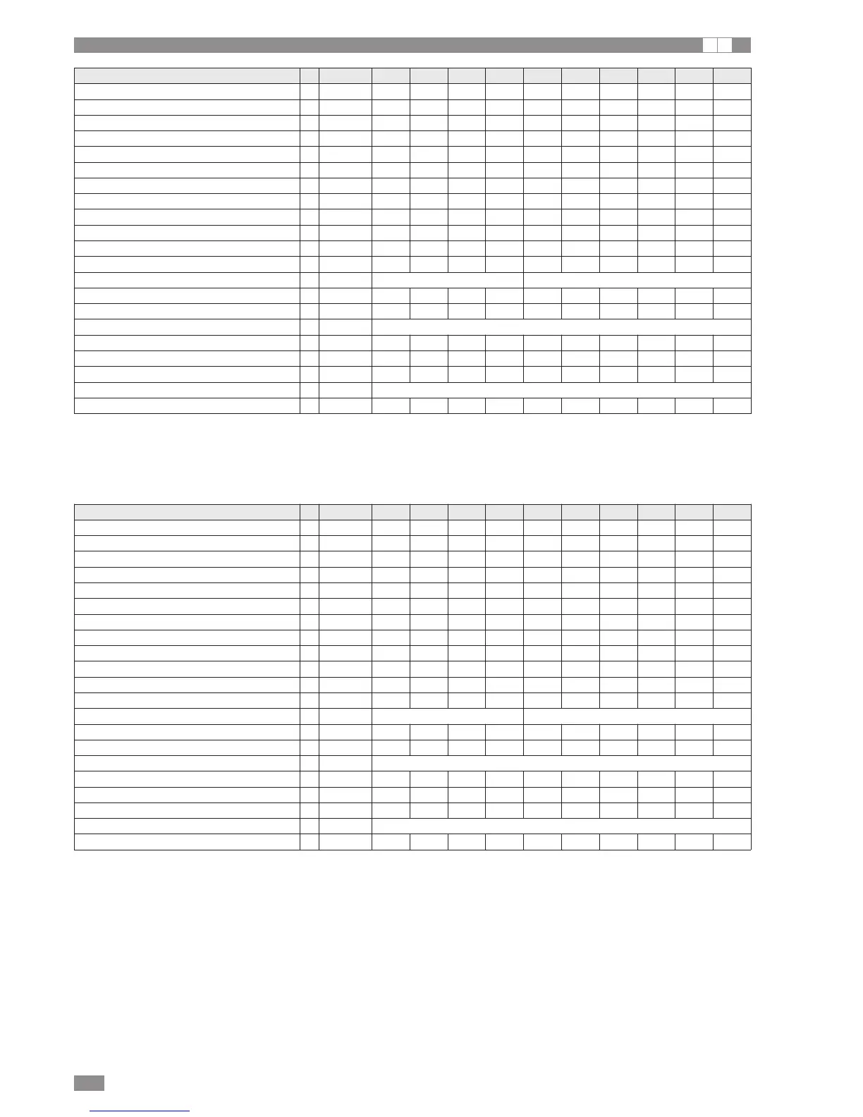
BRA2 without hydronic kit 0021 0025 0031 0041 0021 0025 0031 0041 0051 0061
Cooling capacity 1 [kW] 7,71 9,50 11,5 15,0 7,70 9,0 11,60 15,7 17,9 20,5
Power consumption 1 [kW] 2,29 2,79 3,80 4,60 2,22 2,59 3,55 4,79 5,19 6,03
COP 1 3,37 3,41 3,03 3,26 3,47 3,47 3,27 3,28 3,45 3,40
Cooling capacity 2 [kW] 5,74 7,03 8,68 11,4 5,72 7,10 8,76 11,8 13,3 15,6
Power consumption 2 [kW] 2,22 2,68 3,60 4,33 2,17 2,54 3,32 4,47 5,00 5,57
EER 2 2,59 2,62 2,41 2,63 2,63 2,80 2,64 2,64 2,66 2,80
ESEER 1 3,11 3,22 2,98 3,06 3,21 3,45 3,16 3,13 3,02 3,26
Flow-rate 1 m3/h 1,33 1,63 1,98 2,58 1,32 1,55 2,00 2,70 3,08 3,53
Pressure drop 1 kPa 13 15 16 31 13 14 16 34 36 35
Flow-rate 2 m
3
/h 0,99 1,21 1,49 1,96 0,98 1,22 1,51 2,03 2,29 2,68
Pressure drop 2 kPa 7 8 9 18 7 8 9 19 20 20
Sound power 4 [dBA] 75 75 75 77 75 75 75 77 77 77
Power supply V-N/Ph-Hz 230-1N-50 400-3N-50
No. of compressors 1 1 1 1 1 1 1 1 1 1
No. of circuits 1 1 1 1 1 1 1 1 1 1
Type of compressor Scroll
No. of fans 1 1 1 2 1 1 1 2 2 2
Air flow-rate 1 [m
3
/h] 3000 3400 3400 6450 3000 3400 3400 6450 6000 6350
No. of system heat exchangers 1 1 1 1 1 1 1 1 1 1
Type of system heat exchanger PLATE
System water heat exchanger content l 2 2 2 2 2 2 2 2 2 3
BRA2 with hydronic kit 0021 0025 0031 0041 0021 0025 0031 0041 0051 0061
Cooling capacity 1 [kW] 7,76 9,56 11,6 15,1 7,75 9,1 11,70 15,8 18,0 20,7
Power consumption 1 [kW] 2,21 2,69 3,71 4,48 2,14 2,50 3,45 4,66 5,04 5,91
COP 1 3,51 3,55 3,13 3,37 3,62 3,62 3,39 3,39 3,57 3,50
Cooling capacity 2 [kW] 5,77 7,08 8,73 11,5 5,75 7,15 8,81 11,9 13,4 15,7
Power consumption 2 [kW] 2,16 2,61 3,52 4,26 2,11 2,47 3,24 4,41 4,91 5,45
EER 2 2,67 2,71 2,48 2,70 2,72 2,90 2,72 2,70 2,73 2,88
ESEER 1 3,21 3,35 3,07 3,14 3,33 3,59 3,27 3,23 3,11 3,37
Flow-rate 1 m
3
/h 1,33 1,64 2,00 2,60 1,33 1,56 2,01 2,72 3,10 3,56
Available pressure head 1 kPa 59 50 40 37 60 53 39 33 26 23
Flow-rate 2 m
3
/h 0,99 1,22 1,50 1,98 0,99 1,23 1,52 2,05 2,30 2,70
Available pressure head 2 kPa 72 66 59 51 72 66 59 50 49 47
Sound power [dBA] 75 75 75 77 75 75 75 77 77 77
Power supply V-N/Ph-Hz 230-1N-50 400-3N-50
No. of compressors 1 1 1 1 1 1 1 1 1 1
No. of circuits 1 1 1 1 1 1 1 1 1 1
Type of compressor Scroll
No. of fans 1 1 1 2 1 1 1 2 2 2
Air flow-rate [m
3
/h] 3000 3400 3400 6450 3000 3400 3400 6450 6000 6350
No. of system heat exchangers 1 1 1 1 1 1 1 1 1 1
Type of system heat exchanger PLATE
System water heat exchanger content l 2 2 2 2 2 2 2 2 2 3
(1) outside air 35°C evaporator water IN/OUT 23/18°C
(2) outside air 35°C evaporator water IN/OUT 12/7°C
(3) maximum and minimum operating pressure refer to activation of the pressure switches
(4) sound power based on measurements performed in accordance with ISO 9614 and Eurovent 8/1
Performance in accordance with EN 14511:2013
(1) outside air 35°C evaporator water IN/OUT 23/18°C
(2) outside air 35°C evaporator water IN/OUT 12/7°C
(3) maximum and minimum operating pressure refer to activation of the pressure switches
(4) Sound power based on measurements performed in accordance with ISO 9614 and Eurovent 8/1
Performance in accordance with EN 14511:2013