Model HF-15B High Frequency Spark Tester
HF-15B Instruction Manual – Page 13
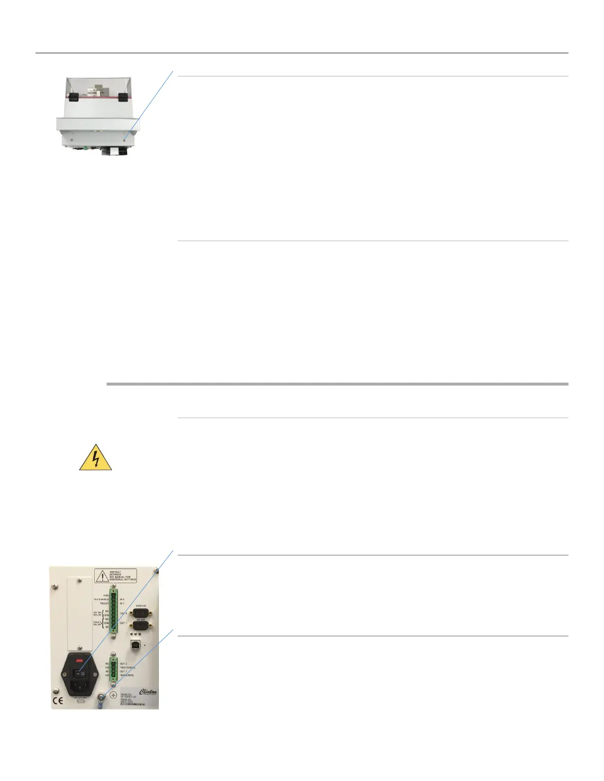
To install RC Display onto the HF-15B
With a screwdriver, remove the 2 Screws on the top of the HF-15B. Align the 2
mounting holes on the RC display mounting bracket with the holes on the
top of the HF-15B. Secure the bracket with the 2 screws that were removed.
Once the display is secure to the top of the unit Connect the 9-pin Serial port
on the rear of the RC display to the 9-pin “DISPLAY” port on the rear of the
HF-15B spark tester using the supplied 1 foot long serial cable.
The RC display can be mounted remotely up to 200 feet away using an
optional serial cable. See Optional Accessories for part numbers.
Provide for ventilation of the Test Module
As with any apparatus producing a spark or electrical corona, the HF-15B Spark
Tester produces ozone in the electrode region. While ozone reverts harmlessly
to oxygen within a few minutes, an external air extraction system is
recommended and should operate whenever the spark tester is in use. The
exhaust of the external air extraction system should be discharged either
outdoors or into some area well away from workers.
Power Wiring
Install an external disconnecting device
Install an external switch or circuit breaker in close proximity to the spark tester
and within easy reach of the operator. The switch or circuit breaker must meet
the relevant requirements of IEC 947-1 and IEC 947-3 and should be marked as
the disconnecting device for the equipment. The rating of the circuit breaker or
fuse should be no greater than 5 amperes.
Caution: Be sure the external disconnecting device is OFF and locked out before
continuing.
Mains Power
Note that the spark tester has a self-adjusting power supply with an operating
voltage range of 100V to 240V at 49-61 Hz.
Ground the Spark Tester
Locate the ground stud on the back panel of the spark tester. Remove the outer
nut and crimp terminal. Crimp a 16 awg. (1, 29 mm
2
, 1, 31 cross section)
stranded insulated wire (preferably green with a yellow stripe) to the crimp
terminal. Fasten this to the ground stud and secure with the keps nut. Connect
the other end to a safety ground system in accordance with EN 60204-1:1993,
Section 5.2, Table 1.