Model HF-15B High Frequency Spark Tester
HF-15B Instruction Manual – Page 16
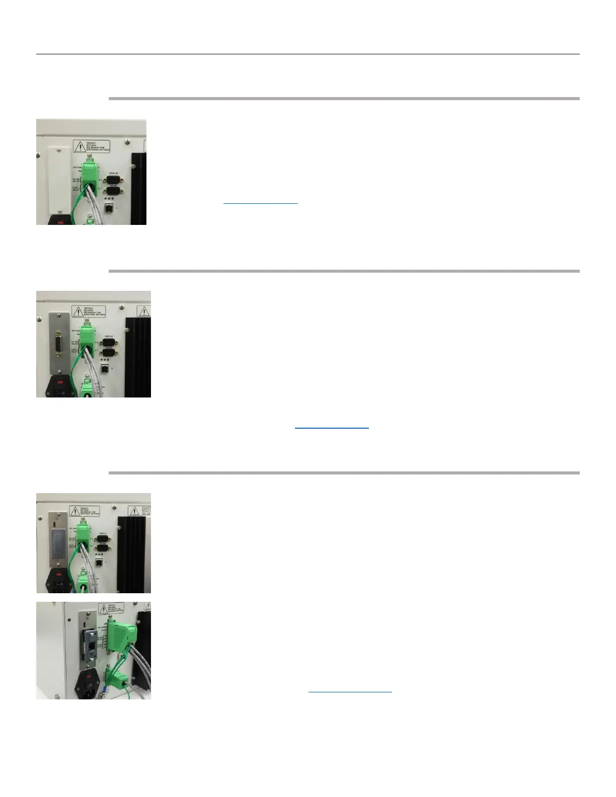
Connecting the Serial RS-485
The model HF-15B is equipped with an RS-485 serial interface allowing the spark
tester to receive commands and exchange information with a PLC or computer.
Programming and control of voltage settings, which can be done manually on
the HF-15B display, can also be done through this interface. Control display
buttons can be disabled when the serial interface is in use. See the section
entitled “RS-485 Interface” for connection and communication information.
The “RS-485” interface connector is located on the rear of the HF-15B directly
under the “Display” connector.
Connecting to the Analog Interface (Optional)
The model HF-15B can be purchased with an optional analog interface. (Model
HF-15BA) The analog interface allows the HF-15B to be controlled by a PLC with
standard analog and Digital I/O. The connecting cable for this interface is not
supplied by Clinton Instrument Company. The cable composition is normally
dictated by the PLC, but ordinarily 22 gauge conductors (individually shielded or
shielded pairs) are required. The maximum length of the cable is also
determined by the equipment the HF-15B is being connected to. However, it is
recommended that the cable length not exceed 10 meters.
See the section entitled “Analog Interface” for the details regarding this
interface.
Installing the CompactCom™ Module (Optional)
The model HF-15B can be purchased with an optional Fieldbus Communications
Interface. (Model HF-15BX) This interface will allow the installation of several
fieldbus options. (DeviceNet, Ethernet IP, Modbus RTU, Modbus TCP, Profibus,
Profinet)
To enable the Fieldbus Interface the proper CompactCom™ module will need to
be installed into the HF-15BX spark tester.
• First remove the Anybus Slot Cover from the rear of the spark tester.
• Remove the CompactCom™ module from the packaging.
• Slide the CompactCom™ module into the open slot on the rear of the
spark tester.
• Secure the CompactCom™ module by tightening the 2 screws.
See the section entitled “Fieldbus Interface” for the details regarding this
interface.