M02R40C8-00 29/07/08 page 48
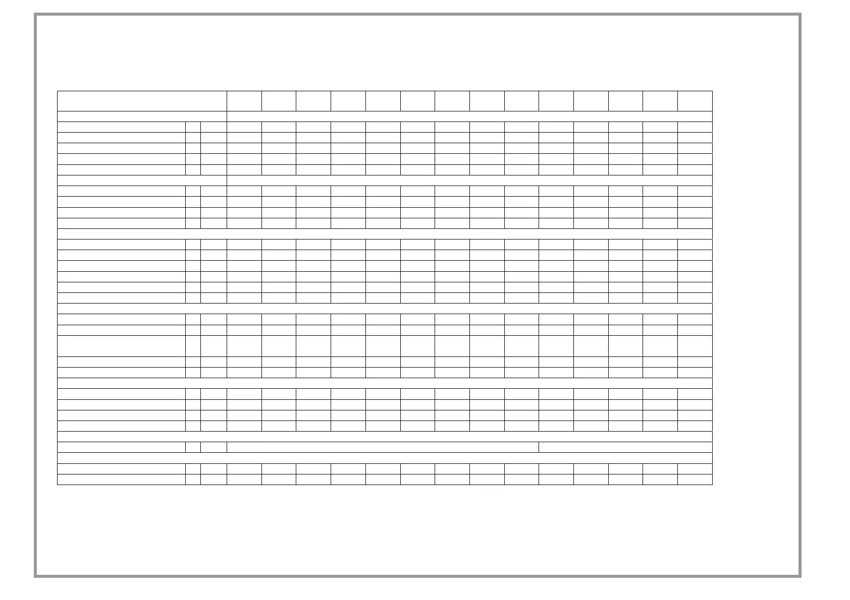
TECHNICAL DATA
Size
17 21 25 31 41 51 61 71 81 91 101 121 131 151
COOLING
Cooling capacity 1 kW 4 4.99 5.58 7.33 8.49 10.4 13.1 15.7 17.3 18.6 22.9 25.7 29.1 33.5
Compressor power input 1 kW 1.69 2.19 2.51 3.19 3.15 4.28 5.14 6.26 6.91 7.74 9.74 10.8 11.5 14.3
Total power input 2 kW 1.76 2.25 2.56 3.34 3.3 4.43 5.45 6.57 7.21 8.04 10 11.2 11.9 14.7
EER 3 2.28 2.22 2.17 2.19 2.57 2.35 2.4 2.38 2.4 2.31 2.28 2.29 2.44 2.28
ESEER 2.56 2.49 2.42 2.47 3.04 2.81 2.8 2.77 2.83 2.66 2.66 2.67 2.8 2.63
HEATING
Heat output 4 kW 4.91 6.09 6.4 8.71 10.1 12.4 14.5 17.1 19.3 21.6 25.2 28.5 33.4 38
Compressor power input 4 kW 1.7 2.05 2.31 2.93 3.17 4.16 4.63 5.57 6.24 6.93 8.13 9.33 10.1 11.9
Total power input 2 kW 1.76 2.11 2.36 3.08 3.32 4.31 4.94 5.88 6.54 7.23 8.44 9.77 10.5 12.3
COP 5 2.79 2.89 2.71 2.83 3.04 2.88 2.94 2.9 2.95 2.99 2.99 2.91 3.18 3.09
COMPRESSOR
Type of compressors 7 ROT ROT ROT ROT
SCROLL SCROLL SCROLL SCROLL SCROLL SCROLL SCROLL SCROLL SCROLL SCROLL
No. of Compressors Nr 1 1 1 1 1 1 1 1 1 1 1 1 1 1
Compressor RPM 6 rpm 1 1 1 1 1 1 1 1 1 1 1 1 1 1
Std Capacity control steps Nr 1 1 1 1 1 1 1 1 1 1 1 1 1 1
Refrigerant charge (C1) 8 kg 2.5 2.6 2.5 2.6 4.7 4.7 5.1 6 6.7 7.5 8.7 9.9 11.4 13.1
Refrigerant circuits Nr 1 1 1 1 1 1 1 1 1 1 1 1 1 1
INTERNAL EXCHANGER
Type of internal exchanger 9 PHE PHE PHE PHE PHE PHE PHE PHE PHE PHE PHE PHE PHE PHE
No. of internal exchangers Nr 1 1 1 1 1 1 1 1 1 1 1 1 1 1
Water flow rate (Internal
Exchanger)
1 l/s 0.19 0.24 0.27 0.35 0.41 0.5 0.62 0.75 0.83 0.89 1.09 1.23 1.39 1.6
Useful pump discharge head 1 kPa 44 39 38 55 52 41 155 146 146 141 134 162 149 136
Water content l 1.1 1.1 1.1 1.2 1.4 1.4 1.1 1.5 1.5 1.8 2.1 2.4 2.7 3.1
EXTERNAL SECTION FANS
Type of fans 10 AX AX AX AX AX AX AX AX AX AX AX AX AX AX
Number of fans Nr 1 1 1 2 2 2 2 2 2 2 2 2 2 2
Standard air flow 1 l/s 502 502 554 1014 1030 1030 1924 1924 2191 2191 2085 2554 2865 2865
Installed unit power kW 0.115 0.115 0.115 0.115 0.115 0.115 0.156 0.156 0.15 0.15 0.152 0.218 0.209 0.209
CONNECTIONS
Water fittings 1" GAS 1 1/4" GAS
HYDRAULIC CIRCUIT
Max water side pressure kPa 550 550 550 550 550 550 550 550 550 550 550 550 550 550
Safety valve calibration kPa 600 600 600 600 600 600 600 600 600 600 600 600 600 600