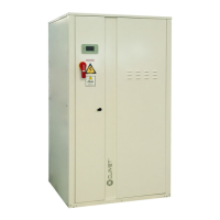
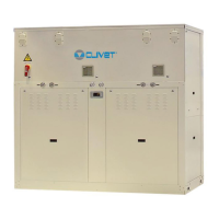
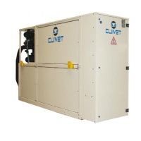
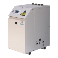
General technical data
Geothermic version
Size
10.2 12.2 14.2 16.2 19.2 22.2 27.2 30.2 35.2 40.2 43.2 45.2 50.2 55.2 60.2 70.2 80.2 90.2 100.2 120.2
Radiant panels
Heating only operation
Heating capacity (EN14511:2013) 1 kW 27,7 32,4 38,3 45,7 54,1 63,9 75,2 85,0 95,7 111 121 130 140 155 174 197 219 247 266 313
Total power input (EN14511:2013) 2 kW 6,61 7,55 9,01 10,6 12,4 15,2 16,8 19,4 22,4 25,6 28,4 30,0 32,5 36,0 40,6 45,4 50,9 59,2 65,0 79,7
COP (EN 14511:2013) 3 4,19 4,29 4,26 4,32 4,35 4,21 4,47 4,38 4,28 4,32 4,27 4,33 4,31 4,32 4,28 4,33 4,30 4,17 4,09 3,93
Terminal units
Heating only operation
Heating capacity (EN14511:2013) 4 kW 27,4 32,1 37,7 45,0 52,8 62,5 73,4 83,2 93,7 108 119 127 138 153 170 193 215 244 263 309
Total power input (EN14511:2013) 2 kW 8,18 9,51 11,2 13,1 15,3 18,3 20,6 23,5 27,1 31,0 34,5 36,5 39,6 43,8 49,6
55,2 61,6 72,4 79,1 97,3
COP (EN 14511:2013) 3 3,35 3,37 3,36 3,44 3,45 3,42 3,56 3,55 3,46 3,49 3,45 3,49 3,48 3,48 3,44 3,49 3,50 3,37 3,32 3,18
Compressor
Type of compressors Scroll Scroll Scroll Scroll Scroll Scroll Scroll Scroll Scroll Scroll Scroll Scroll Scroll Scroll Scroll Scroll Scroll Scroll Scroll Scroll
No. of compressors Nr 22222222222222222222
Std Capacity control steps Nr 33233332333333232332
Oil charge (C1) l 3,00 3,00 3,00 6,00 6,00 6,00 7,00 7,00 8,00 10,1 11,5 11,0 11,0 13,1 12,6 12,6 12,6 12,6 12,6 12,6
Refrigerant charge kg 3,8 4,1 4,4 7,4 7,7 8,5 9,4 11 13 14 15 15 18 21 22 24 25
28 29 31
Refrigeration circuits Nr 11111111111111111111
Internal exchanger
Type of internal exchanger 5 PHE PHE PHE PHE PHE PHE PHE PHE PHE PHE PHE PHE PHE PHE PHE PHE PHE PHE PHE PHE
No. of internal exchangers Nr 1 1 1 11111111111111111
Water ow-rate (Heat side) l/s 1,31 1,53 1,79 2,14 2,51 2,97 3,49 3,96 4,46 5,15 5,66 6,06 6,56 7,26 8,11 9,17 10,24 11,61 12,51 14,71
External exchanger
Type of external exchanger 5 PHE PHE PHE PHE PHE PHE PHE PHE PHE PHE PHE PHE PHE PHE PHE PHE PHE PHE PHE PHE
No. of external exchangers Nr 11111111111111111
111
Water ow-rate (Cool side) l/s 1,66 1,95 2,29 2,76 3,24 3,83 4,52 5,13 5,72 6,63 7,25 7,78 8,42 9,33 10,37 11,80 13,19 14,73 15,80 18,25
Connections
Water ttings (standard units) 1’ 1/4 1’ 1/4 1’ 1/4 1’ 1/4 1’ 1/4 1’ 1/4 2’1/2 2’1/2 2’1/2 2’1/2 2’1/2 2’1/2 2’1/2 2’1/2 2’1/2 2’1/2 2’1/2 2’1/2 3’3’
Water ttings (Larger units) 2’ 2’ 2’ 2’ 2’ 2’ 3’ 3’ 3’ 3’ 3’ 3’ 3’ 3’ 3’ 3’ 3’ 3’ 4’ 4’
Water circuit
Maximum water side pressure 6 MPa 1,0 1,0 1,0 1,0 1,0 1,0 1,0 1,0 1,0 1,0 1,0 1,0 1,0 1,0 1,0 1,0 1,0 1,0 1,0 1,0
Power supply
Standard power supply V
400/3/50
400/3/50
400/3/50 400/3/50 400/3/50 400/3/50
400/3/50 400/3/50
400/3/50 400/3/50 400/3/50 400/3/50 400/3/50 400/3/50 400/3/50 400/3/50 400/3/50 400/3/50 400/3/50 400/3/50
Dati riferiti alle seguenti condizioni: acqua allo scambiatore interno 30/35°C. Acqua allo scambiatore esterno 0/-3°C. Dati riferiti al funzionamento con miscela di acqua e glicole propilenico al 30% lato sorgente. Dati prestazionali calcolati in riferimento alla norm
Not: The unit only works in hot mode.
1. Data referred to the following conditions: Hot side exchanger water 30/35 °C. Cold side exchanger water 0/-3 °C. Operation with 30% cold side mixture of water and propylene glycol. Performance data calculated with reference to EN14511:2013
2. The total power draw is calculated by adding the compressor’s power draw + the draw required to overcome the internal cold and hot side pressure drops + the control circuit power draw
3. COP (EN 14511:2013) heating performance coecient. Ratio between delivered heating capacity and power input in compliance with EN 14511:2013
4. Data referred to the following conditions: Hot side exchanger water 40/45°C. Cold side exchanger water 0/-3 °C. Operation with 30% cold side mixture of water and propylene glycol. Performance data calculated with reference to EN14511:2013
5. PHE = plate exchanger
6. Conditions for the circuit on the utility side and the circuit on the source side. In congurations with hydronic units, the maximum
pressure on the water side is 600 kPa.

 Loading...


