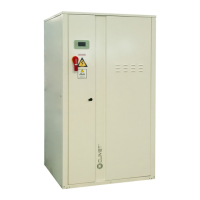
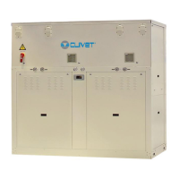
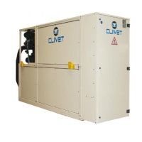
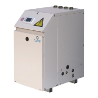
General technical data
Groundwater version
Size
10.2 12.2 14.2 16.2 19.2 22.2 27.2 30.2 35.2 40.2 43.2 45.2 50.2 55.2 60.2 70.2 80.2 90.2 100.2 120.2
Radiant panels
Heating only operation
Heating capacity (EN14511:2013) 1 kW
37,1 42,8 51,7 60,1 71,3 83,8 101 114 132 149 164 177 193 209 238 268 302 340 371 437
Total power input (EN14511:2013) 2 kW
6,78 8,04 9,68 11,4 13,2 16,2 18,2 21,4 24,4 27,8 31,3 32,8 35,6 39,5 44,6 50,7 57,3 64,9 70,2 84,8
COP (EN 14511:2013) 3
5,47 5,33 5,34 5,29 5,42 5,16 5,54 5,35 5,39 5,36 5,24 5,41 5,41 5,30 5,35 5,30 5,28 5,24 5,28 5,16
Cooling only operation
Cooling capacity (EN14511:2013) 6 kW
41,9 57,8 57,5 66,8 79,6 91,3 112 126 147 166 183 198 216 234 266 297 335 377 406 473
Total power input (EN14511:2013) 2 kW
6,67 8,28 10,2 11,9 13,7 16,8 18,4 21,2 25,3 28,4 32,7 34,2 37,4 41,4 47,1 54,0 62,4 67,4 74,6 88,8
EER (EN 14511:2013) 7
6,27 5,76 5,67 5,63 5,81 5,45 6,10 5,95 5,82 5,84 5,58 5,80 5,78 5,64 5,63 5,51 5,37 5,59 5,45 5,33
Terminal units
Heating only operation
Heating power (EN14511:2013) 4 kW
35,8 41,4 49,6 57,8 68,6 81,0 96,7 109 126 143 157 169 184 200 227 257 290 328 355 420
Total power input (EN14511:2013) 2 kW
8,27 9,79 11,6 13,5 15,7 19,2 21,8 25,3 28,9 32,8 36,7 38,7 41,9 46,5 52,4 59,2 66,7 76,6 83,4 101
COP (EN 14511:2013) 3
4,33 4,23 4,26 4,29 4,37 4,23 4,43 4,32 4,35 4,35 4,27 4,37 4,39 4,30 4,33 4,34 4,34 4,28 4,25 4,16
Cooling only operation
Cooling capacity (EN14511:2013) 8 kW
30,8 35,4 42,7 49,6 59,1 68,4 83,8 94,4 109 123 135 147 159 172 197 221 249 280 305 356
Total power input (EN14511:2013) 2 kW
6,45 7,63 9,22 10,8 12,5 15,6 17,5 20,4 23,5 26,6 29,8 31,5 34,1 37,7 42,7 48,2 54,7 61,5 68,4 82,4
EER (EN 14511:2013) 7
4,77 4,64 4,63 4,61 4,72 4,39 4,80 4,63 4,62 4,63 4,53 4,65 4,68 4,58 4,60 4,59 4,55 4,56 4,46 4,32
ESEER (EN 14511:2013)
9
6,31 6,20 5,65 5,52 5,71 5,51 6,19 6,05 6,03 6,02 5,78 6,00 5,97 5,79 5,62 5,78 5,48 5,52 5,48 5,31
Radiators
Heating only operation
Unit with one ON/OFF pump (HYGSW1) 5
33,2 38,8 46,3 53,9 63,2 74,6 88,6 101 116 132 146 156 170 186 210 237 267 303 330 395
Total power input (EN14511:2013) 2
10,3 12,2 14,4 16,6 19,3 23,0 26,7 30,4 35,1 39,6 44,6 47,0 51,1 56,4 63,8 71,2 79,8 93,1 102 125
COP (EN 14511:2013) 3
3,22 3,17 3,21 3,25 3,27 3,24 3,32 3,32 3,30 3,32 3,27 3,31 3,33 3,29 3,29 3,33 3,35 3,26 3,24 3,17
Compressor
Type of compressors
Scroll Scroll Scroll Scroll Scroll Scroll Scroll Scroll Scroll Scroll Scroll Scroll Scroll Scroll Scroll Scroll Scroll Scroll Scroll Scroll
No. of compressors No
2222222222222222222 2
Std Capacity control steps No
3323333233333323233 2
Oil charge l
3,00 3,00 3,00 6,00 6,00 6,00 7,00 7,00 8,00 10,1 11,5 11,0 11,0 13,1 12,6 12,6 12,6 12,6 12,6 12,6
Refrigerant charge kg
3,8 4,1 4,4 7,4 7,7 8,5 9,4 11 13 14 15 15 18 21 22 24 25 28 29 31
Refrigeration circuits No
1111111111111111111 1
Internal exchanger
Type of internal exchanger 10
PHE PHE PHE PHE PHE PHE PHE PHE PHE PHE PHE PHE PHE PHE PHE PHE PHE PHE PHE PHE
No. of internal exchangers No
1111111111111111111 1
Water ow-rate (Cool side) 8 l/s
1,50 1,70 2,10 2,40 2,80 3,30 4,00 4,50 5,20 5,90 6,50 7,00 7,70 8,30 9,40 10,6 12,0 13,5 14,7 17,1
External exchanger
Type of external exchanger 10
PHE PHE PHE PHE PHE PHE PHE PHE PHE PHE PHE PHE PHE PHE PHE PHE PHE PHE PHE PHE
No. of external exchangers No
1111111111111111111 1
Water ow rate (Heat Side) 8 l/s
1,80 2,00 2,50 2,90 3,40 4,00 4,80 5,50 6,30 7,10 7,80 8,50 9,20 10,0 11,4 12,8 14,4 16,3 17,8 20,9
Connections
Water ttings (Standard units)
1’ 1/4 1’ 1/4 1’ 1/4 1’ 1/4 1’ 1/4 1’ 1/4 2’1/2 2’1/2 2’1/2 2’1/2 2’1/2 2’1/2 2’1/2 2’1/2 2’1/2 2’1/2 2’1/2 2’1/2 3’ 3’
Water ttings (Larger units)
2’ 2’ 2’ 2’ 2’ 2’ 3’ 3’ 3’ 3’ 3’ 3’ 3’ 3’ 3’ 3’ 3’ 3’ 4’ 4’
Water circuit
Maximum water side pressure 11 MPa
1,0 1,0 1,0 1,0 1,0 1,0 1,0 1,0 1,0 1,0 1,0 1,0 1,0 1,0 1,0 1,0 1,0 1,0 1,0 1,0
Power supply
Standard power supply V
400/3/50 400/3/50 400/3/50 400/3/50 400/3/50 400/3/50 400/3/50 400/3/50 400/3/50 400/3/50 400/3/50 400/3/50 400/3/50 400/3/50 400/3/50 400/3/50 400/3/50
400/3/50
400/3/50 400/3/50
Note: The unit can operate in cooling-only or in heating-only mode.
1. Data referred to the following conditions: Cold side exchanger water 30/35°C. Hot side exchanger water 10/7°C. Performance data
calculated with reference to EN14511:2013
2. The total power draw is calculated by adding the compressor’s power draw + the draw required to overcome the internal cold and
hot side pressure drops + the control circuit power draw
3. COP (EN 14511:2013) heating performance coecient. Ratio between delivered heating capacity and power input in compliance
with EN 14511:2013
4. Data referred to the following conditions: Cold side exchanger water 40/45°C. Hot side exchanger water 10/7°C. Performance data
calculated with reference to EN14511:2013
5. Data referred to the following conditions: Cold side exchanger water 50/55°C. Hot side exchanger water 10/7°C. Performance data
calculated with reference to EN14511:2013
6. Data referred to the following conditions: Cold side exchanger water 23/18°C. Hot side exchanger water 30/35 °C. Performance data
calculated with reference to EN14511:2013
7. EER (EN 14511:2013) cooling performance coecient. Ratio between delivered cooling capacity and power input in compliance
with EN 14511:2013
8. Data referred to the following conditions: Cold side exchanger water 12/7°C. Hot side exchanger water 30/35 °C. Performance data
calculated with reference to EN14511:2013
9. ESEER calculated per EUROVENT, for installations with terminal units with water produced at 7 °C and constant hot side ow
10. PHE = plate exchanger
11. Conditions for the circuit on the utility side and the circuit on the source side. In congurations with hydronic units, the maximum
pressure on the water side is 600 kPa.

 Loading...


