Z4II & Z8II: Installation and User Guide 5
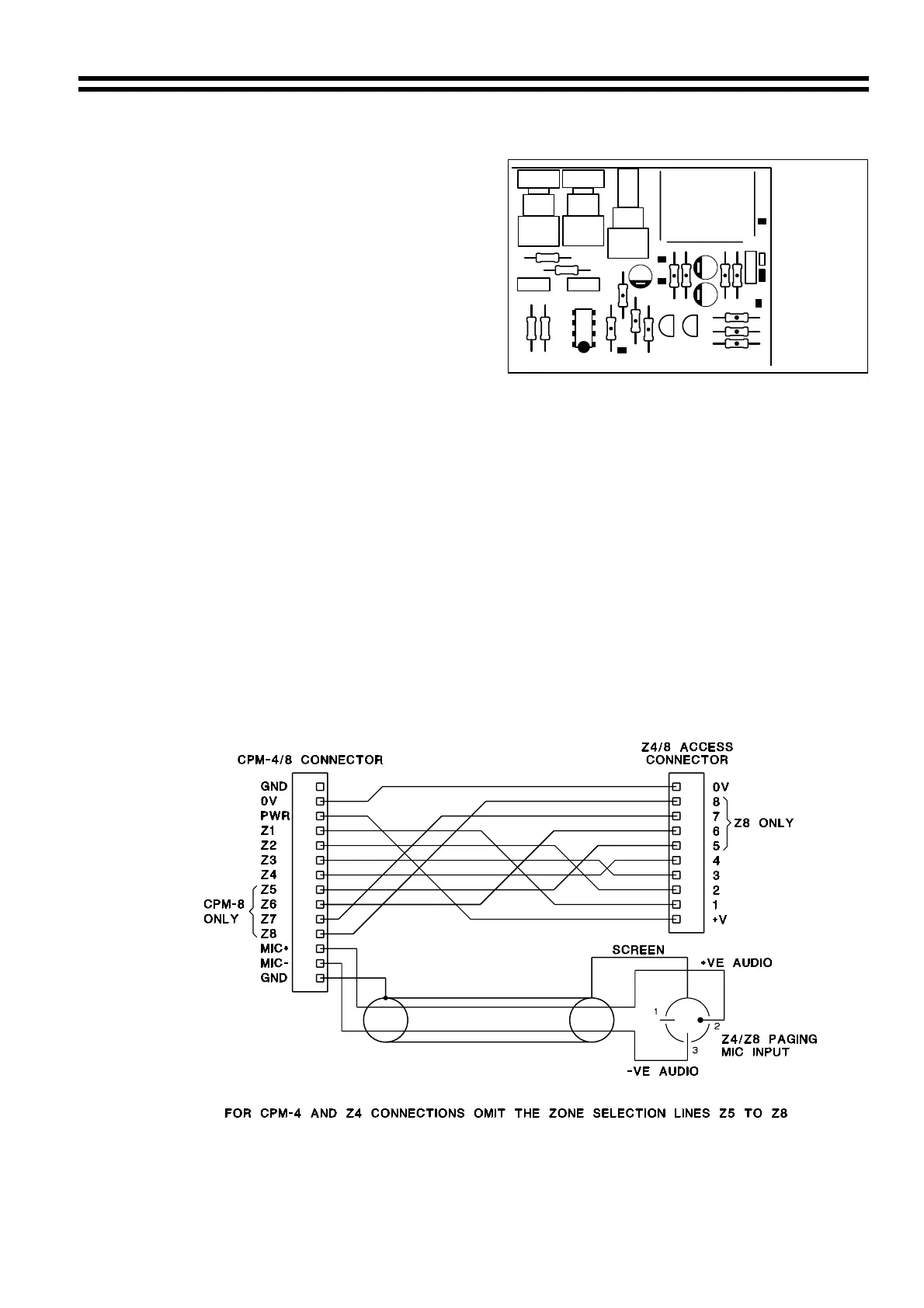
Location of Jumper J1
For balanced microphones, connect the
cable screen to pin 1, the in-phase signal
(+) to pin 2 and the reverse phase signal
MICROPHONE
PHANTOM
POWER
MIC INPUT
SOCKET
HF
LF
GAIN
VR2VR3
VR1
C10
J2 R13
R14
C9
R
8
C
6
C7
R
1
1
SK1
C5
C2
R
7
R
2
C1
J1
ON
R
1
OFF
C3
C4
R3
R4
R5
R
9
T
R
2
T
R
1
IC1
R
1
5
T
L
0
7
2
(-) to pin 3. For unbalanced microphones,
connect a wire link from pin 1 (ground) to
pin 3 inside the XLR cable mounted plug;
use pin 1 as ground (cable screen) and pin
2 as hot. Do not use the phantom power
facility with unbalanced terminations.
When setting the jumper(s) please ensure
that you:
• Remove the mains cable from the rear of the product before removing the top panel.
• Only reassemble the unit using screws identical to the original parts.
• Use a microphone that requires phantom power.
11 Paging Microphone
A dedicated paging microphone input is provided with adjacent gain control and equalisation
pre-sets. Once the input gain control has been set the paging mic level of each zone can be
optimised by adjusting the front panel mounted pre-set level controls. The Cloud CPM-4 &
CPM-8 zone paging microphones are available as an optional accessory, both microphones
feature zone selection switches allowing paging to all four or eight zones in any combination;
in addition a ‘call all’ button is provided for announcements to all zones. The zone select
buttons have push/on and push/off operation however, they can be internally configured to
automatically reset after an announcement has been made. A CPM microphone can be
internally configured to activate a pre-announcement chime, as well as an internal sounder
so that the chime is audible to the operator.
When using a single CPM paging microphone use the wiring diagram shown below: -
Wiring a CPM Microphone to a Z4 or Z8 Venue Mixer
Up to 5 CPM paging microphones can be used with a Z4 or Z8 Venue Mixer, when wiring
more than one CPM paging microphone either the Z4 or Z8 Venue Mixers please use the
diagram on the following page: -
30/05/03 V8