Z4-8MK4 Installation and User Guide v1.214
In systems using multiple mixers in conjunction with PM
Series microphones, it is possible to redene how the mixer
interprets the zones being selected on the microphone by
applying “zone offset”; this allows the microphone to address
a higher-numbered set of zones. This topic is covered in full
detail under “Zone Offset” in the Setting Up & Operation
section of the manual; see page 19.
IMPORTANT - Please refer to the PM Series Installation
Guide for full information regarding maximum cable length,
buss terminations and current requirements.
The earlier Cloud CDPM Series of paging microphones is also
compatible with the Digital Paging Interface.
Connecting a PM4/4SA/8/8SA/12/16 paging mic via
the analogue interface
Two connections are required: the paging mic audio signal
should be connected to the PAGING MIC Input ([7] on
“Description of rear panel” on page 9) and the control
cable to the 10-pin ZONE ACCESS SWITCHING port
([12] on “Description of rear panel” on page 9). The pinout
of the ZONE ACCESS SWITCHING port is given below:
FUNCTION
Z8MK4
PIN NO.
Z4MK4
PIN NO.
0 V 1 1
Zone 1 2 2
Zone 2 3 3
Zone 3 4 4
Zone 4 5 5
Zone 5 6
Zone 6 7
Zone 7 8
Zone 8 9
+12 V 10 6
Standard two-core screened audio cable may be used for
the audio signal, and stranded multicore cable with an overall
screen for the control cable. The number of cores required in
the latter will be determined by the model of PM microphone
being used and whether the mixer is a Z8MK4 or Z4MK4;
however, note that one additional core will be required if the
PM Series microphone is to be powered from the Zone Mixer.
(Note that ‘-SA’ versions of PM Series microphones cannot
be powered by the Z8MK4 or Z4MK4, and require an external
PSU).
Connections on the PM microphone are made via the rear
cable access glands and screw terminal blocks on the internal
PCB (TERM1, TERM4 and TERM8 in the example shown
below). Full connection details and notes on power supply
considerations can be found in the PM Series Installation and
User Guide.
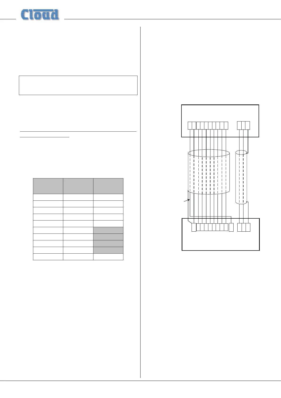
The following diagram shows both the cable connections
between a PM8 and a Z8MK4. Note that the DC power
supply connection will not be required if the PM microphone
is powered independently (either by a local PSU or via the
network from another PM unit).
TERM8TERM2TERM1
HOTCOLD GND
Z1 Z2 Z3
Z4
Z5 Z6 Z7
Z8
Z1 Z2 Z3 Z4 Z5 Z6 Z7 Z8
Z1 Z2 Z3
Z4
Z5 Z6 Z7
Z8
Z1 Z2 Z3 Z4 Z5 Z6 Z7 Z8
0 V
+ V
PAGING MIC INPUTZONE ACCESS
HOT
COLDGND
0 V + V
PM8 PAGING MICROPHONE
Z8
MK4 MIXER
y required if
ophone is to
wered from the mixer
For individual zone paging as described above, the paging
mic priority trigger should be selected to ‘SW’ by moving J5
on each zone sub-board in the Zone MIxer. See “Paging mic
priority” on page 19 for further information.
Connecting a PM1 paging mic
The PM1 is a simple, passive paging microphone suitable
for situations where announcements are always made to
the same zone(s). It can be connected directly to Z8MK4/
Z4MK4 zone mixers’ analogue paging interface, the control
cable being wired to the pin(s) of the PAGING ACCESS
SWITCHING port corresponding to the zone(s) in which
announcements are required. Any or all of the zones may be
paralleled if multiple zones need to operate from the PM1.