Z4-8MK4 Installation and User Guide v1.224
APPENDIX
The Z8MK4 and Z4MK4 will nd application in many types of premises, including shops, bars, hotels, schools, conference centres,
ofces, etc.
Application example 1
A typical example using most of the Zone Mixer’s facilities is given below.
ZONE 5
ZONE 3
ZONE 2
ZONE 6
ZONE 8
ZONE 4
ZONE 7
ZONE 1
ZONE 5
ZONE 3
ZONE 2
ZONE 6
ZONE 8
ZONE 4
ZONE 7
ZONE 1
ZONE 5
ZONE 3
ZONE 2
ZONE 6
ZONE 8
ZONE 4
ZONE 7
ZONE 1
OUTPUTSREMOTE SOURCE + LEVEL PORTS
FACILITY PORTS
INPUT 1
INPUT 6
INPUT 4
INPUT 2
INPUT 3
INPUT 5
MIC 1
MIC 2
PAGING MIC
PAGING ACCESS
CD PLAYER
MEDIA
HUB
PC/
WEBSTREAM
DAB
RADIO
FREEVIEW
RECEIVER
AREA 1
AREA 2
AREA 3
POWER
AMPLIFIERS
OTHER
AREAS
PM PAGING
MICROPHONE
RSL-6
LM-2
RL-1
LOCAL
MICS
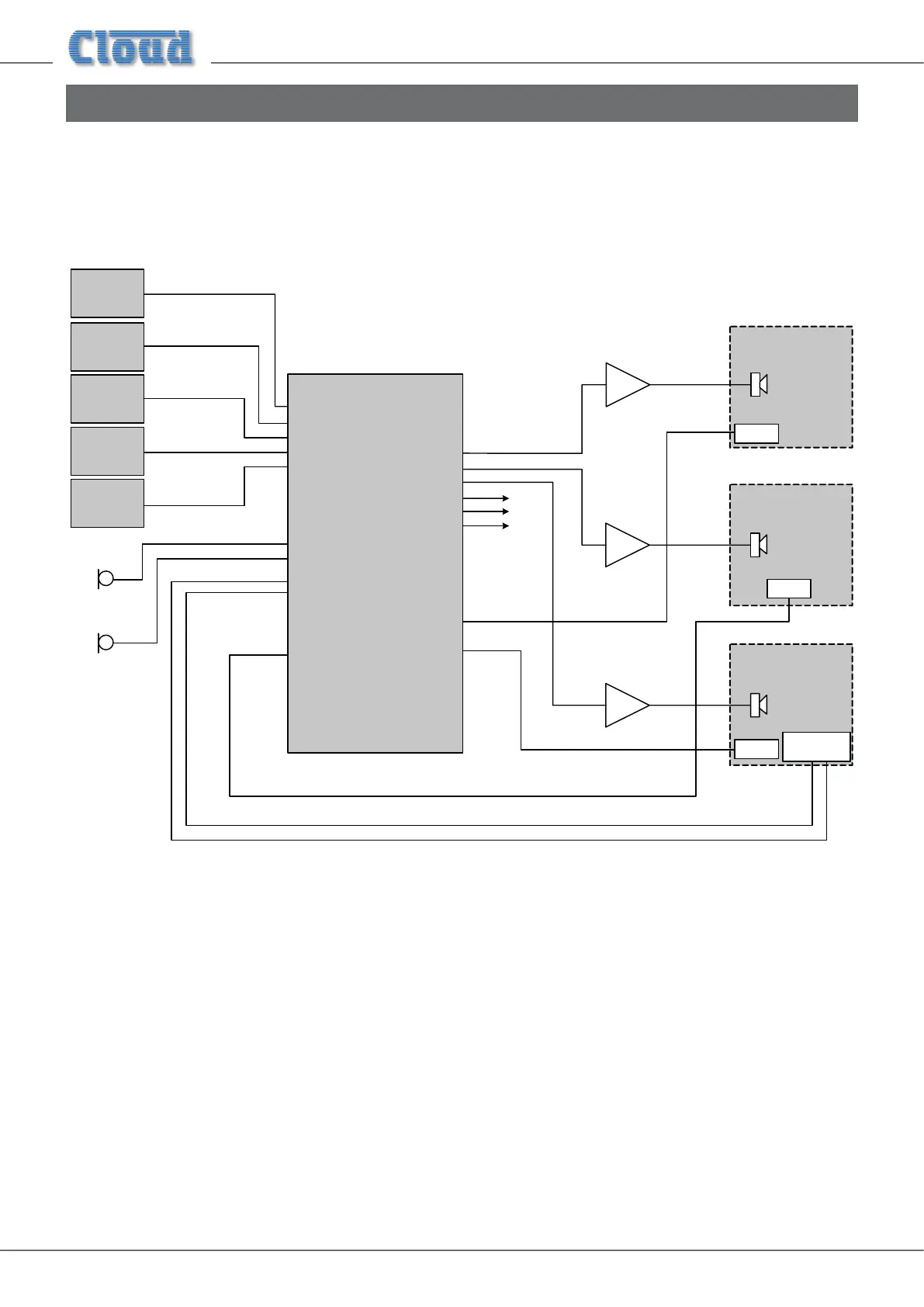
The diagram depicts a system where four possible music (or other audio) sources are made available to three or more zones
(areas). Only three zones are shown for clarity. Points to note:
• Area 1 and Area 3 have remote control plates installed: an RSL-6 Series (music level and source) in Area 1 and an RL-1
Series (music level only) in Area 3. These are wired to the REMOTE SOURCE+LEVEL Ports for their respective zone
outputs.
• Area 2 includes an LM-2 mic/line input module wired to Zone 2’s FACILITY PORT This would allow both a
microphone and a portable stereo music source to be connected in that area. The LM-2 also provides music source and
level control; note that the LM-2 does not require a second connection to the REMOTE SOURCE+LEVEL Port to
enable this.
• Area 3 has a Cloud PM paging microphone, which would be used to originate voice messages to any of the areas. The
paging level to Area 3 (if required) would be adjusted on installation to be at a level that does not cause feedback.
Application example 2
This example shows how two Zone Mixers – in this case one Z8MK4 and one Z4MK4 – can be used in conjunction with the
Cloud Digital Paging Interface to allow a PM12 Paging Microphone to correctly address all 12 zones.
ZONE 5
ZONE 3
ZONE 2
ZONE 6
ZONE 8
ZONE 4
ZONE 7
ZONE 1
OUTPUTS
DIGITAL PAGING
INTERFACE
IN
THRU
PM12
ZONE 3
ZONE 2
ZONE 4
ZONE 1
OUTPUTS
DIGITAL PAGING
INTERFACE
IN
THRU
Z8MK4
Z4MK4
SW2 settings:
Termination: OFF
Zone Offset: 0
SW2 settings:
Termination: ON
Zone Offset: 8
ZONE 5
ZONE 3
ZONE 2
ZONE 6
ZONE 8
ZONE 4
ZONE 7
ZONE 1
ZONE 11
ZONE 10
ZONE 12
ZONE 9
The Digital Paging Interface THRU port of the Z8MK4 is connected to the IN port of the Z4MK4 using Cat 5 cabling. The
important points to note are:
• The buss termination should be set OFF in the Z8MK4, as it is not at the “end” of the network chain. However, the
termination in the Z4MK4 should be set ON.
• Zone Offset should be set to 8 in the Z4MK4 (and left at zero in the Z8MK4). This will allow zone buttons 9 to 12 on the
PM12 to correctly address the four zones driven by the four-channel Zone Mixer.
• The diagram only shows the Digital Paging Interface and output connections for simplicity. In practice, all music sources
and microphone inputs would need to be paralleled to both Zone Mixers. Direct parallel connection will probably prove
satisfactory for the line inputs, but the use of a two-way passive or active mic splitter is recommended for use with the
microphone inputs.