Z4-8MK4 Installation and User Guide v1.2 9
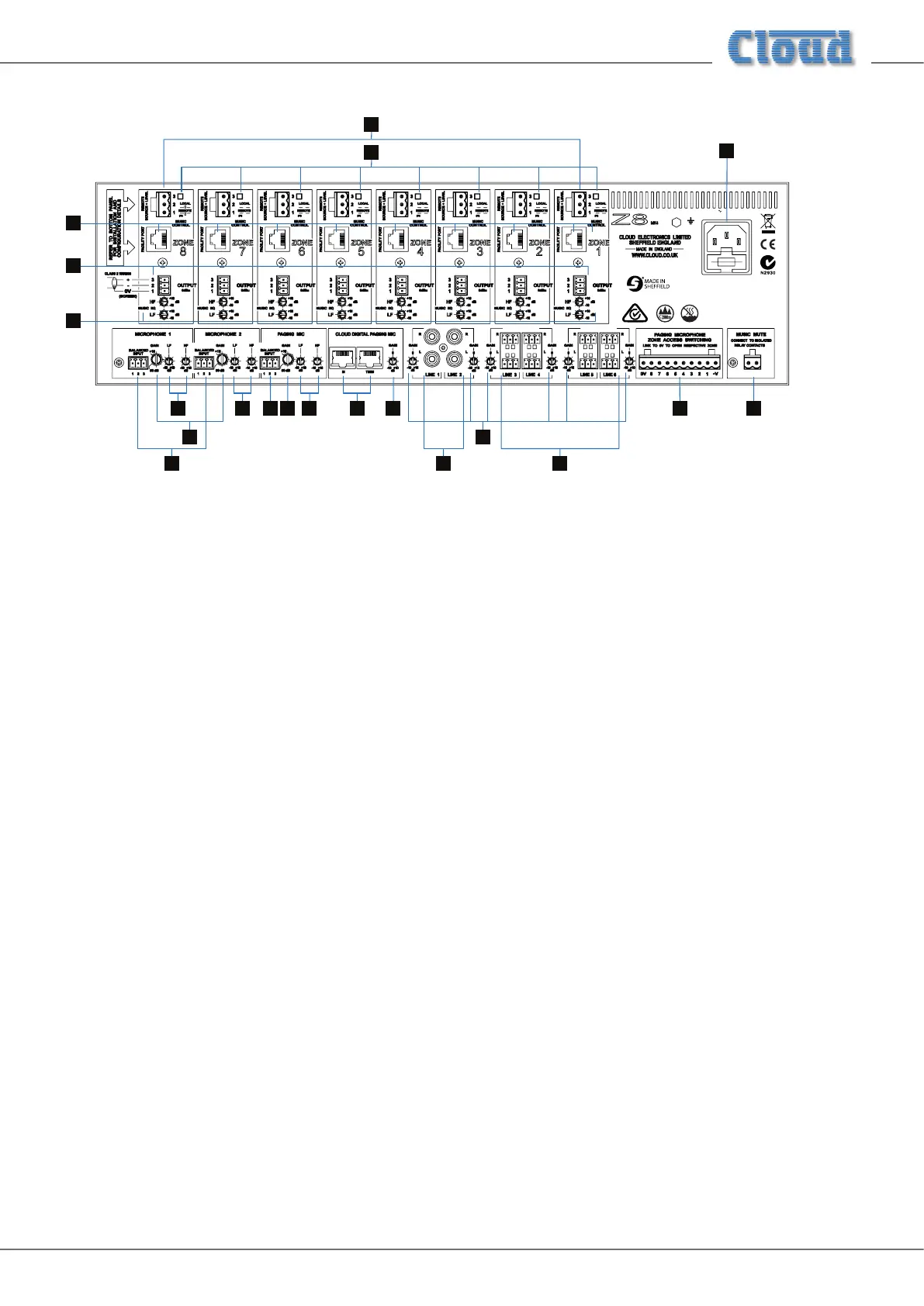
Description of rear panel
13
14
15
16
17
19
35
6 6 9 10
11 12 18
7 8
Z8
FUSE
MK4
47 - 63Hz 10.6W
FULL ACCESSORIES 28.5 WATTS
85V - 253V
CAUTION:
CAUTION:
ATTENTION:
REPLACE WITH SAME TYPE T1AH 250V FUSE.
TO REDUCE THE RISK OF ELECTRIC SHOCK,
GROUNDING OF THIS APPARATUS
MUST BE MAINTAINED.
UTILISER UN FUSIBLE DE RECHANGE DE MÊME
TYPE DE T1AH 250V.
Note - The rear panel of the Z8MK4 is shown above. Note that the Z4MK4 is identical, except that it only has output connections
for Zones 1 - 4.
1. LINE 1 and 2 – two pairs of RCA (phono) sockets for connection of music sources with unbalanced outputs. Inputs
are stereo, summed internally to mono. See “Music Sources” on page 10.
2. LINE 3 to 6 – four 3-pin 3.5 mm-pitch screw-terminal connectors for connection of music sources with balanced
outputs. Inputs are stereo, summed internally to mono. See “Music Sources” on page 10.
3. GAIN – preset trim control for each line input, providing +/-10 dB of gain adjustment for input level matching.
See page 17.
4. MICROPHONE 1 and 2 – 2 balanced microphone inputs on 3-pin 3.5 mm-pitch screw-terminal connectors.
See page 11.
5. GAIN – preset mic gain control for each microphone input, gain range 10 to 50 dB. See page 17.
6. LF and HF – preset EQ controls for each microphone input. See page 17.
7. PAGING MIC – dedicated balanced input (3-pin 3.5 mm-pitch screw-terminal connector) for paging mic.
See page 13.
8. GAIN – preset gain control for paging mic input; as [5]. See page 18.
9. HF and LF – paging mic EQ; as [6]. See page 19.
10. CLOUD DIGITAL PAGING MIC – two RJ45 sockets (IN and THRU) for direct connection of Cloud PM and CDPM
Series digital paging microphones. See “Cloud Digital Paging Mics” on page 18.
11. GAIN – preset gain trim control for digital paging mic: provides +/-10 dB of adjustment.
12. PAGING MICROPHONE ZONE ACCESS SWITCHING – 10-pin (Z8MK4) or 6-pin (Z4MK4) 5 mm-pitch screw-
terminal connector for contact-closure paging access, per-zone. See “Paging System connections” on page 13.
13. OUTPUTS – 8 balanced outputs* for each zone on 3-pin 3.5 mm-pitch screw-terminal connector. See page 19.
14. MUSIC EQ – HF & LF EQ adjustment of music signal in zone. See page “EQ” on page 17.
15. FACILITY PORT – 8-pin RJ45 per-zone, for connection of remote input modules and other functions. See page 12.
16. REMOTE SOURCE + LEVEL ports – 3-pin 5 mm-pitch screw terminal connector per-zone, for connection of RL-1/
RSL-6 remote control plates. See page 15.
17. MUSIC CONTROL – switches determining whether front panel music source and level controls will remain active
when remote control plates are connected (per-zone). See page 15.
18. MUSIC MUTE – 2-pin 5 mm-pitch screw terminal connector for connection of external emergency muting relay
(e.g., re control panel). See page 16.
19. Mains – Fused IEC receptacle for AC mains (includes storage for spare fuse). See page 10.
* Only 4 zone outputs on Model Z4MK4 (Items [13] to [17])