Z4-8MK4 Installation and User Guide v1.216
Connecting an RSL-6 Series remote control plate
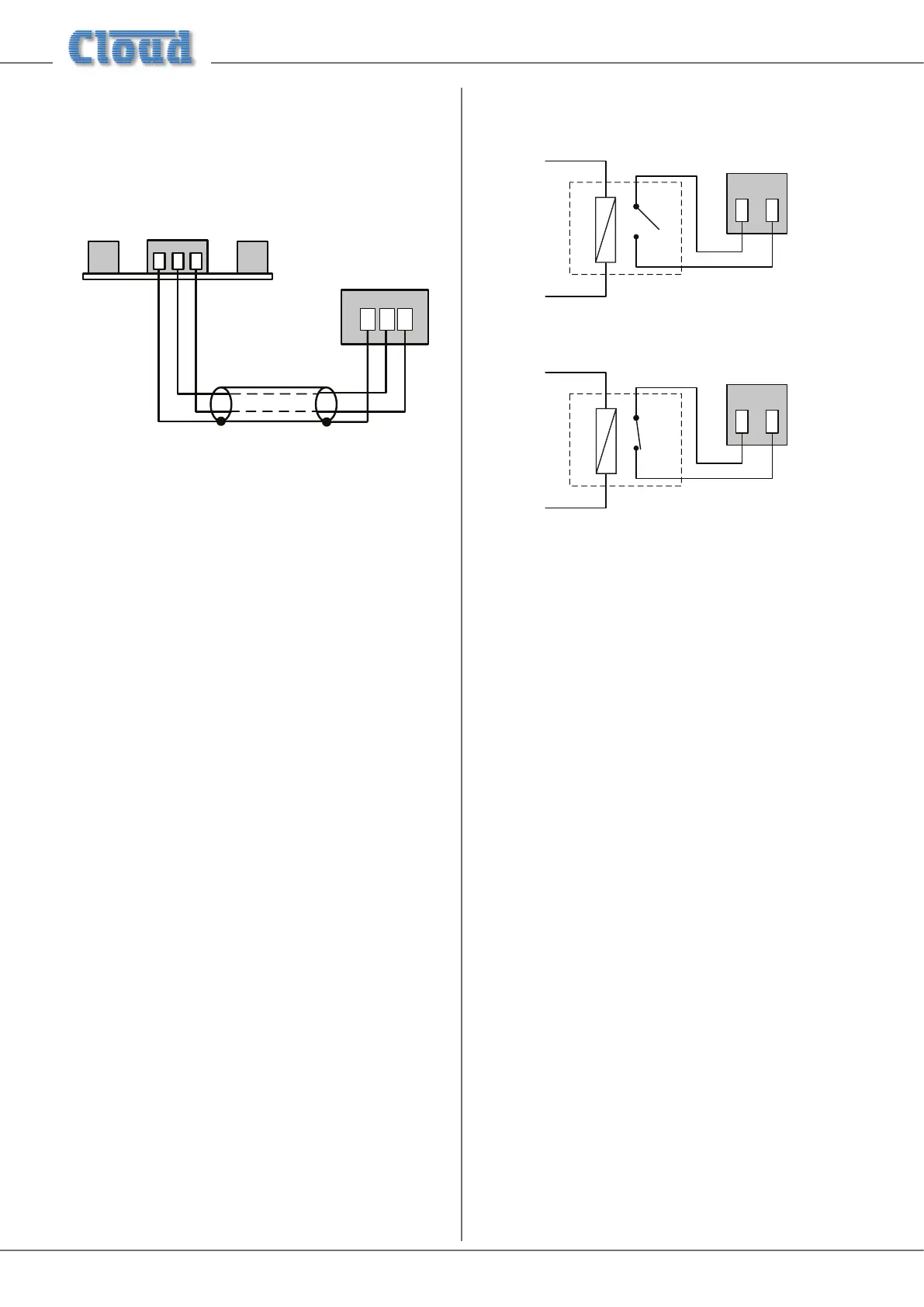
Wire the remote control plate as shown below. Twin-and-
screen cable should be used. Maximum reliable cable run is
100 m.
1
2
3
REMOTE SOURCE & LEVEL CONTROL WIRING
RSL-6
USE TWO-CORE SCREENED CABLE
1
2
3
REMOTE SOUCE+LEVEL
PORT
Before the RSL-6 will operate, the zone’s REMOTE
SOURCE+LEVEL port must be enabled by setting the
adjacent push-button switch ([18] on page 9) to REMOTE
(i.e., pressing it in). In this setting, the zone’s front panel Music
Level and Music Source controls become inoperative.
Music Mute
External muting of music is available at the MUSIC MUTE
connector. National or Local Authority regulations governing
such systems may require that normal programme material
(i.e., music) should be muted in an emergency, to ensure that
any emergency messages are clearly audible.
The Music Mute input is a 2-pin 5 mm-pitch screw-terminal
connector. It should be connected to the appropriate alarm
output on whichever building management system registers
the alarm (typically the Fire System). The alarm output must
be volt-free; if no such output is available, an intermediate
relay or other isolation device must be installed between the
alarm output and the Music Mute input.
The Mute input can be set to operate on either normally
open (N/O) or normally closed (N/C) contacts via an internal
DIP switch (see “PCB jumper location and settings” on page
26). The factory default setting is N/O, thus requiring
a short-circuit to be applied across the two pins of the
connector for muting to occur.
Visual indication of muting being activated is given by the
Mute LED on the front panel.
12
MUSIC MUTE
INPUT
RELAY
NORMALLY OPEN (N/O)
CONNECTION
12
INPUT
RELAY
NORMALLY CLOSED (N/C)