EasyManua.ls Logo

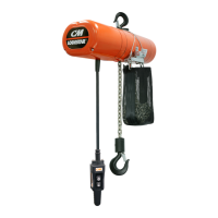
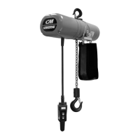
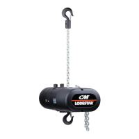
CM Lodestar R User Manual

Default Icon
128 pages
To Next Page IconTo Next Page
Page #1 background imageLoading...
Page #1 background image
Before installing hoist, fi ll in the information below.
Model Number
Serial No.
Pur
chase Date
V
oltage
Rated Load
RATED LOADS 1/8 TO 3 TONNES
125 KG TO 3000 KG
Follow all instructions and warning for inspecting,
maintaining and operating this hoist.
The use of any hoist presents some risk of personal injury
or property damage. That risk is greatly increased if proper
instructions and warnings are not followed. Before using
this hoist, each operator should become thoroughly familiar
with all warnings, instructions and recommendations in this
manual. Retain this manual for future reference and use.
Forward this manual to operator. Failure to operate equipment
as directed in manual may cause injury.
ELECTRIC CHAIN HOIST
OPERATING, MAINTENANCE
& PARTS MANUAL
P/N: 00001996 (REV AC) 627NH October 2014
Distributed by Ergonomic Partners
Sales@ErgonomicPartners.com
www.ErgonomicPartners.com
Tel: (314) 884-8884

Table of Contents

Other manuals for CM Lodestar R

Questions and Answers:

CM Lodestar R Specifications

General IconGeneral
BrandCM
ModelLodestar R
CategoryChain Hoists
LanguageEnglish

Summary

SAFETY PRECAUTIONS

HOIST OPERATION GUIDELINES

GENERAL INFORMATION

SPECIFICATIONS

Details about the Lodestar Electric Chain Hoist models, capacities, and speeds.

INSTALLATION

INSTALLING THE SUSPENSION

Procedures for attaching suspension assemblies to different hoist models.

ATTACHING LOAD CHAIN

POWER SUPPLY AND ELECTRICAL CONNECTIONS

POWER PHASING

Checking motor rotation direction for three-phase hoists to prevent damage.

LIMIT SWITCH ADJUSTMENTS

SETTING UPPER LIMIT SWITCH

Steps to adjust the upper limit switch for correct stopping position.

SETTING LOWER LIMIT SWITCH

Procedures for adjusting the lower limit switch for proper hook positioning.

REFERENCE WIRING DIAGRAMS

ASSEMBLY INSTRUCTIONS

REMOVAL AND INSTALLATION OF LOAD CHAIN

Detailed steps for replacing or installing the hoist's load chain.

WARRANTY AND LIMITATION OF REMEDY AND LIABILITY

ELECTROMOTIVE IMPULSE® •G+ MINI ADJUSTABLE FREQUENCY DRIVES

OPERATING INSTRUCTIONS

SAFETY PROCEDURES

INSPECTION AND MAINTENANCE

WIRING DIAGRAMS

VFD CONTACTOR PLATE ASSEMBLIES

PROGRAMMING THE ADJUSTABLE FREQUENCY DRIVE

USING THE KEYPAD

Accessing drive functions via keypad, entering configuration data.

KEYPAD FUNCTIONS

Describes keypad display, indicators, and keys for drive operation.

Impulse•G+ Mini Structure of Parameters

ELECTROMOTIVE SYSTEMS LIMITED WARRANTY

Related product manuals