EasyManua.ls Logo

CM Lodestar RRS User Manual

Default Icon
128 pages
To Next Page IconTo Next Page
Page #1 background imageLoading...
Page #1 background image
Before installing hoist, fi ll in the information below.
Model Number
Serial No.
Pur
chase Date
V
oltage
Rated Load
RATED LOADS 1/8 TO 3 TONNES
125 KG TO 3000 KG
Follow all instructions and warning for inspecting,
maintaining and operating this hoist.
The use of any hoist presents some risk of personal injury
or property damage. That risk is greatly increased if proper
instructions and warnings are not followed. Before using
this hoist, each operator should become thoroughly familiar
with all warnings, instructions and recommendations in this
manual. Retain this manual for future reference and use.
Forward this manual to operator. Failure to operate equipment
as directed in manual may cause injury.
ELECTRIC CHAIN HOIST
OPERATING, MAINTENANCE
& PARTS MANUAL
P/N: 00001996 (REV AC) 627NH October 2014
Distributed by Ergonomic Partners
Sales@ErgonomicPartners.com
www.ErgonomicPartners.com
Tel: (314) 884-8884

Table of Contents

Other manuals for CM Lodestar RRS

Question and Answer IconNeed help?

Do you have a question about the CM Lodestar RRS and is the answer not in the manual?

CM Lodestar RRS Specifications

General IconGeneral
BrandCM
ModelLodestar RRS
CategoryChain Hoists
LanguageEnglish

Summary

SAFETY PRECAUTIONS

GENERAL INFORMATION

Specifications

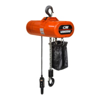
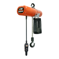
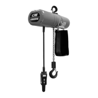
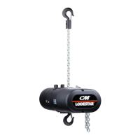
Technical details and model variations of the Lodestar Electric Chain Hoist.

ACCESSORIES

INSTALLATION

Installing the Suspension

Instructions for attaching hook or lug suspensions to various hoist models.

ATTACHING LOAD CHAIN

Chain Attachment Procedures

Detailed steps for attaching load chain to single, triple reeved, and specific models.

POWER SUPPLY AND ELECTRICAL CONNECTIONS

CHECKING FOR ADEQUATE VOLTAGE AT HOIST

Low Voltage Signs and Solutions

Identifies symptoms of low voltage and provides solutions and warnings.

CHECKING LIMIT SWITCH OPERATION

Limit Switch Operation Check

Steps to verify the proper function of upper and lower limit switches.

OPERATING INSTRUCTIONS

General Operation Guidelines

Explains load-limiter function, adjustable limit switches, and two-speed operation.

Hoist Operation Procedures

Basic steps for lifting loads, including overhead positioning and off-center loading avoidance.

SAFE OPERATING INSTRUCTIONS AND PROCEDURES

Safe Operation Guidelines

Lists essential do's and do not's for safe hoist operation.

INSPECTION

INSPECTING THE LOAD CHAIN

Load Chain Inspection Procedures

Steps for inspecting load chain for wear, cracks, and elongation.

MAINTENANCE

Hoist Lubrication Details

Specific lubrication points and recommendations for hoist gears, bearings, and chain.

BRAKE ADJUSTMENTS

LIMIT SWITCH ADJUSTMENTS

Setting Upper Limit Switch

Step-by-step guide for adjusting the upper limit switch for various models.

SETTING LOWER LIMIT SWITCH

ELECTRICAL DATA

ASSEMBLY INSTRUCTIONS

Load Chain Removal and Installation

Procedures for removing and installing hoist load chains.

CUTTING CHAIN

DC BRAKE - SINGLE MODELS

COMPLETE CONTROL CORD AND STATION ASSEMBLY SINGLE SPEED HOIST CONTROL STATION

COMPLETE CONTROL CORD AND STATION ASSEMBLY TWO SPEED HOIST CONTROL STATION

CONTACTOR PLATE ASSEMBLY FOR USE WITH DC BRAKE AND TRANSFORMER 110/115-1-50/60 MODELS A, AA, B, C, E, F & H

CONTACTOR PLATE ASSEMBLY FOR USE WITH DC BRAKE 1-SPEED, DUAL VOLTAGE UNITS 220/230-380/415/460-3-50/60 MODELS A, AA, B, C, E, F & H

CONTACTOR PLATE ASSEMBLY FOR USE WITH DC BRAKE 2-SPEED UNITS 220/230-3-50/60 MODELS A-2, AA-2, B-2, C-2, E-2, F-2 & H-2

CONTACTOR PLATE ASSEMBLY FOR USE WITH DC BRAKE 2-SPEED UNITS 550/575-3-50/60 MODELS A, AA, B, C, E, F & H

CONTACTOR PLATE ASSEMBLY FOR USE WITH DC BRAKE 1-SPEED MODELS J, L, R & RT

CONTACTOR PLATE ASSEMBLY FOR USE WITH DC BRAKE 1-SPEED UNITS 220/230-1-50/60 MODELS J, L, R & RT

CONTACTOR PLATE ASSEMBLY FOR USE WITH DC BRAKE 2-SPEED UNITS 220/230-380/415/460-3-50/60 MODELS J, JJ, L, LL, R, RR, RT & RRT

CONTACTOR PLATE ASSEMBLY FOR USE WITH DC BRAKE 2-SPEED UNITS 550/575-3-50/60 MODELS J, JJ, L, LL, R, RR, RT & RRT

CONTACTOR PLATE ASSEMBLY FOR USE WITH DC BRAKE 2-SPEED UNITS 220/230-3-50/60 MODELS J-2, JJ-2, L-2, LL-2, R-2, RR-2, RT-2 & RRT-2

CONTACTOR PLATE ASSEMBLY FOR USE WITH DC BRAKE 2-SPEED UNITS 380/415/460-3-50/60 MODELS J-2, JJ-2, L-2, LL-2, R-2, RR-2, RT-2 & RRT-2

CONTACTOR PLATE ASSEMBLY FOR USE WITH DC BRAKE 2-SPEED UNITS 550/575-3-50/60 MODELS J-2, JJ-2, L-2, LL-2, R-2, RR-2, RT-2 & RRT-2

CONTACTOR PLATE ASSEMBLY FOR USE WITH DC BRAKE 1-SPEED, DUAL VOLTAGE UNITS 220/230-380/415/460-3-50/60 MODELS: RRS

CONTACTOR PLATE ASSEMBLY 550/575-3-50/60 FOR USE WITH DC BRAKE 2-SPEED UNITS MODELS: RRS

LUBRICANTS

RECOMMENDED SPARE PARTS

WARRANTY

Warranty and Limitation of Remedy and Liability

Outlines the product warranty terms, limitations, and liabilities.

Related product manuals