C.M.C. n.v. - Airmaster R1 installation guide – base unit – V1.1 – MANY0317A.00
Page 12 of 41
6. Installation
This part is necessary for the designer willing to use the Airmaster R1. It shows how an R1
can be integrated into an electrical circuit. Chapter 8 “Putting into operation” gives some
directions that should be known in production. We strongly advise to use these assembly
instructions.
6.1 Cable connector types
The cable connector must match with the connectors populated on the Airmaster R1. Please
refer to appendix 3 for more information.
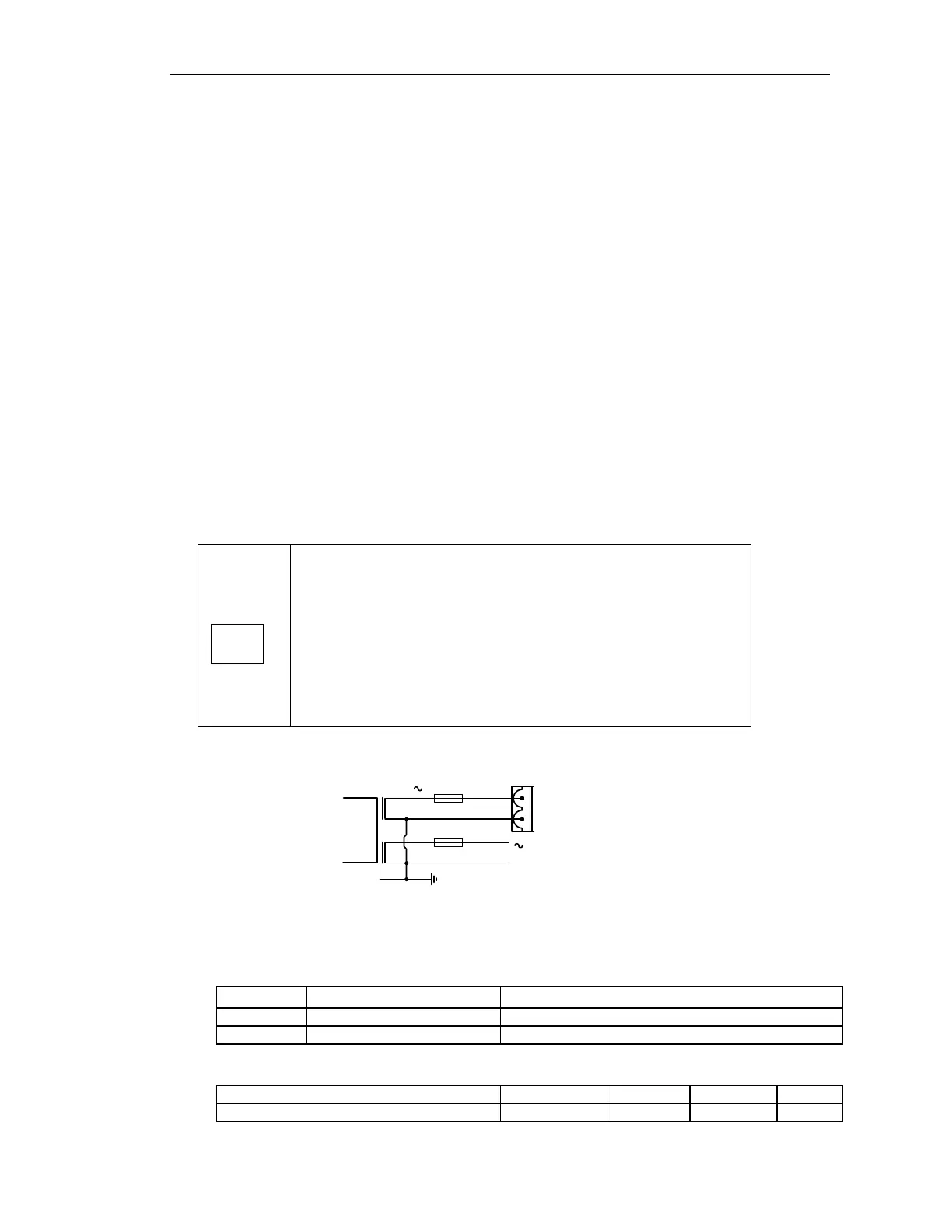
6.2 Power supply and fusing
Power supply and fusing is an important part of the installation. The supply can be with an
AC voltage or with a DC voltage. The maximum variation on the 24V ac is +-20%. The
nominal DC voltage is 24V dc. The variation on the DC voltage is 20Vdc to 36Vdc.
The input voltage ratings for UL are: 24 Vac or 24 Vdc
(Limited Voltage/Current).
“The devices shall be supplied by an isolating device such that
the maximum open circuit voltage potential available to the
circuit is not more than 24Vdc/ac and the current is limited to a
value not exceeding 8 amperes measured after 1 minute of
operation. A secondary fuse or other such secondary circuit
protection rated 4A in accordance with the UL248 series shall
be used to limit the available current.”
F1: 4A T (Timelag, slow blow) fuse
Connector X10
Pin Name function
1 SUPPLY(+) Supply input: AC or positive (+) DC
2 SUPPLY(-) Supply input: AC or negative (-) DC
min typ max dim
AC input voltage
+V
24V
50VA
F1 (T)
L1
L3
T1
0V
V2
0V
X10
1
2
UL
 Loading...