C.M.C. n.v. - Airmaster R1 installation guide – base unit – V1.1 – MANY0317A.00
Page 16 of 41
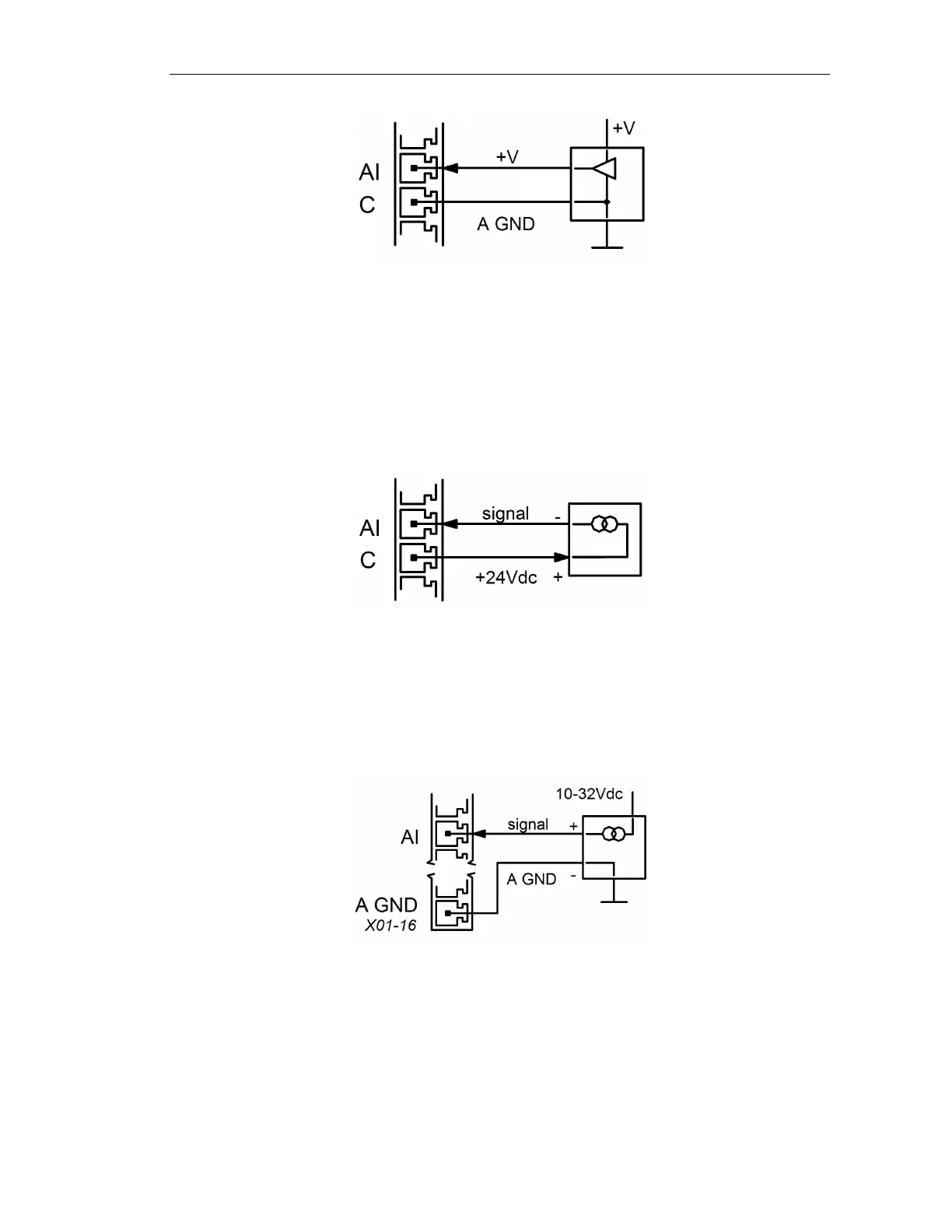
+V means a positive voltage to analogue ground (A GND). The signal voltage can be
different from the supply voltage of the external sensor.
6.3.3 ACM type 3: 4-20mA input (standard)
4..20mA loop powered
This configuration uses the available 24Vdc source on the base unit. No additional power
source is necessary. This configuration is recommended.
4..20mA self powered
In the self powered configuration the sensor uses an external DC power supply source. For
reference with the supply, the A GND must be connected to the Airmaster R1 analogue
ground pin.
6.3.4 ACM type 4: 4-20mA earth referenced (special type)
This ACM can be used with a special 4..20mA current sensor (with GND connected to
ground).
 Loading...