C.M.C. n.v. - Airmaster R1 installation guide – base unit – V1.1 – MANY0317A.00
Page 5 of 41
National and international directives and standards can change in time.
Please check them at a regular basis, and make modifications to your
equipment where this should be necessary.
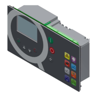
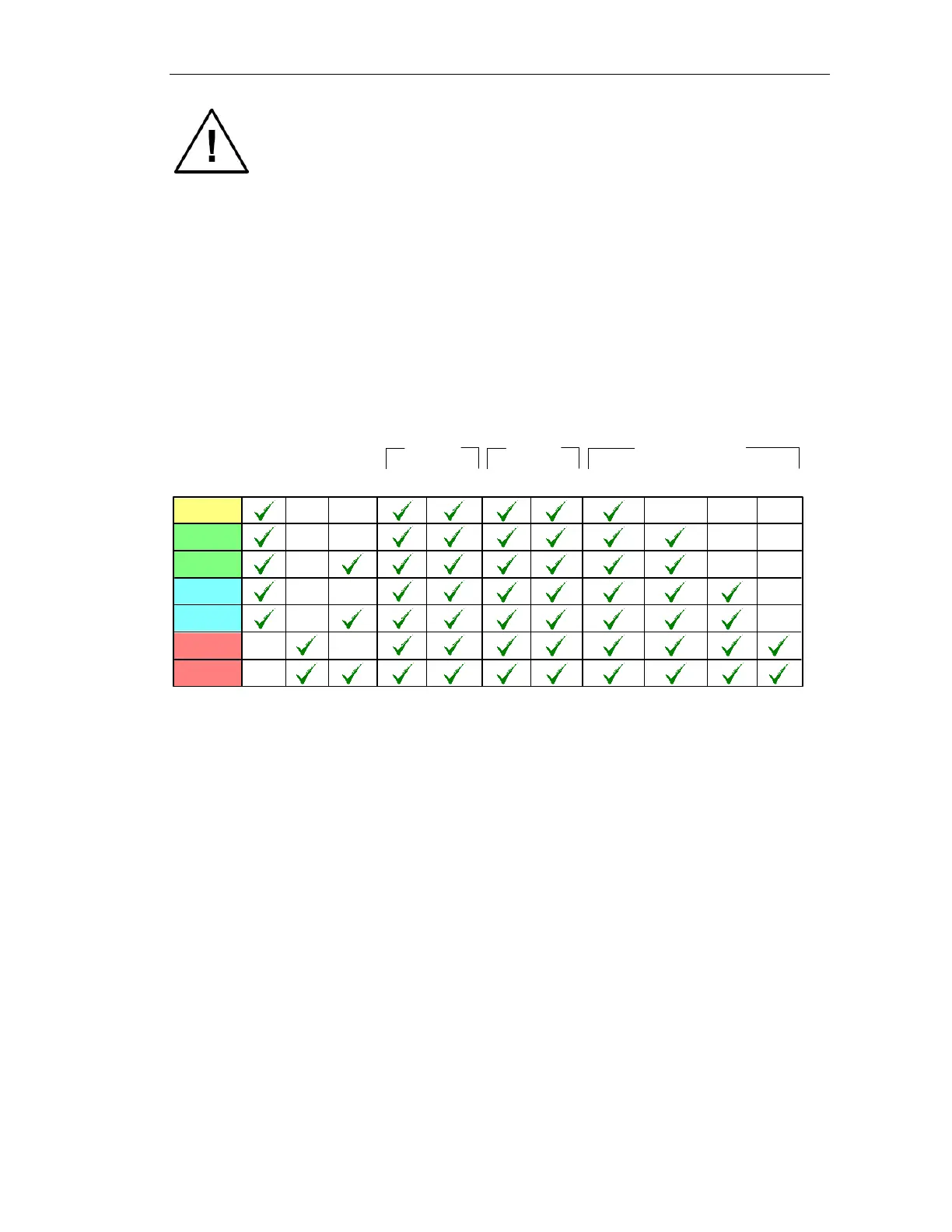
2. Models
2.1 Basic versions
There are 7 basic versions available of the Airmaster R1 base unit. The following table
indicates the differences. The analogue conditioning modules (see further) must be added to
the basic version. The separate RS-485 communication channel to a standard HMI is not
indicated in the table below.
256K 512K
2 x
4-20mA
6 x
Relay
8 x
Digital
4 x
Analogue
RS485(1)
RS485(2) RS232
CAN
Real
Time
Clock
Memory
Communications
Inputs
Outputs
Flash
R1 - 10
R1 - 20
R1 - 25
R1 - 30
R1 - 35
R1 - 40
R1 - 45
R1
 Loading...