CMT2300A
Rev 1.0 | Page37/46
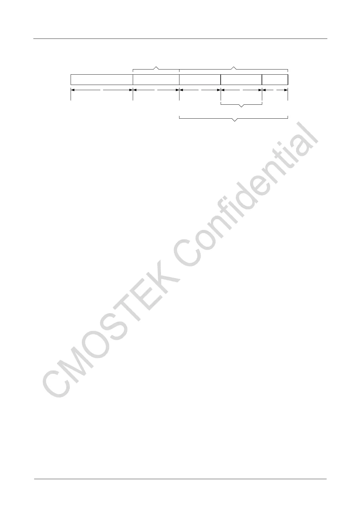
Preamble Sync Word
Node ID Data CRC
Payload/CRC
1 2 3
4 5
Manchester/Whiten/FEC(7,4)
Manchester
Data-Only CRC
图 22.Fixed length packet
Rx processing
In the packet mode, the output data from the demodulator will be transferred to the packet handler for decoding, and then filled in
the FIFO. The packet handler provides a variety of decoding mechanisms and options to determine the validity of the data. These
can reduce the work load of the MCU. The typical package mode control sequence for the MCU is:
1. Configures GPIO usingthe CUS_IO_SEL register.
2. Setup the interruptsusingCUS_INT1_CTL, CUS_INT2_CTL and CUS_INT_EN registers.
3. Send thego_rx command.
4. Reads the RX FIFO according to the relevant interrupts.
5. Sends the go_sleep/go_stby/go_rfs command to stop the receiving and save the power.
6. Clears the packet interruptsusingCUS_ INT_CLR1 and CUS_INT_CLR2 registers.
Tx processing
In the packet mode, MCU can fill the data in the FIFO in advance in the STBY and TFS state, or fill them in the FIFO while the
chip sends the data, or use the combination of the above two methods. The typical Txpacket mode control sequence for the MCU
is:
1. Configures GPIO usingthe CUS_IO_SEL register
2. Sends go_stby/go_tfs command when the data is filled in FIFO in advance.
3. Sends go_tx command.
4. Writes the data into FIFO according to the relevant interrupt status.
5. Sends go_sleep/go_stby/go_rfs command to save power.
CMT2300A has rich configurable hardware resources of FIFO, packet and their interrupts, which makes it compatible with most
of the similar RF products in the market. For more details please refer to the interface of RFPDK and “AN143-CMT2300A FIFO
and Data Packet Usage Guideline”.