CMT2310A
Rev 1.0E | Page32/50
Interrupt for CSMA complete
Signal channel sensing interrupt.
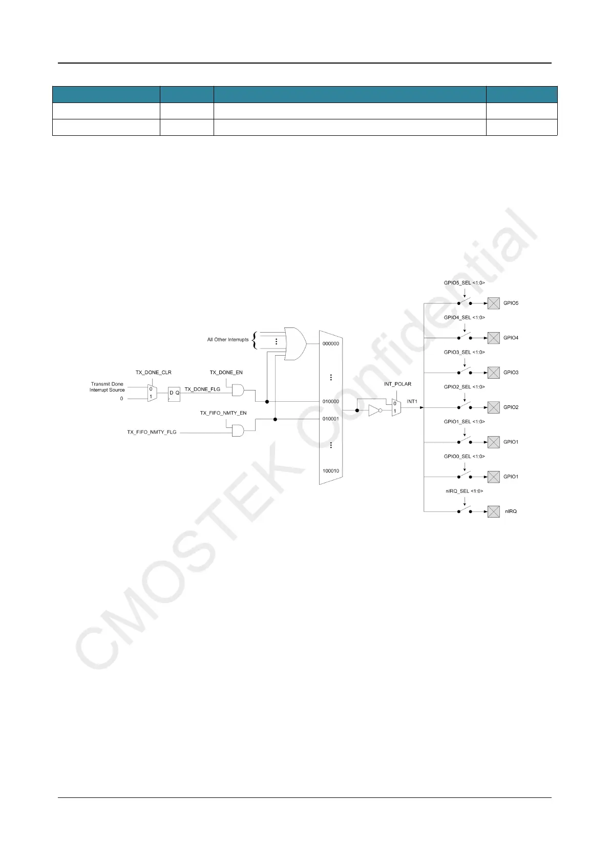
By default, Interrupt is enabled when register value is 1. Users can set the INT_POLAR register bit to 1 to make all interrupts to
be enabled when the register value is 0. Take INT 1 as an example, the control and selection of two different types of interrupt
sources is shown in the figure below. The control and mapping of INT 1 and INT 2 is the same and both can be mapped to any
GPIO. INT_MIX is the only source for INT 3, which can only be mapped to GPIO 0 and GPIO 2. In application, users can choose
either to map all interrupt sources to the interrupt port through INT_MIX (identify which interrupt is valid by checking the interrupt
flag) or directly map a specific interrupt source to the interrupt port.
Figure 25. CMT 2310A INT 1 Interrupt Mapping Diagram
 Loading...