10. Analog to Digital Conversion (ADC)
10.1 ADC general
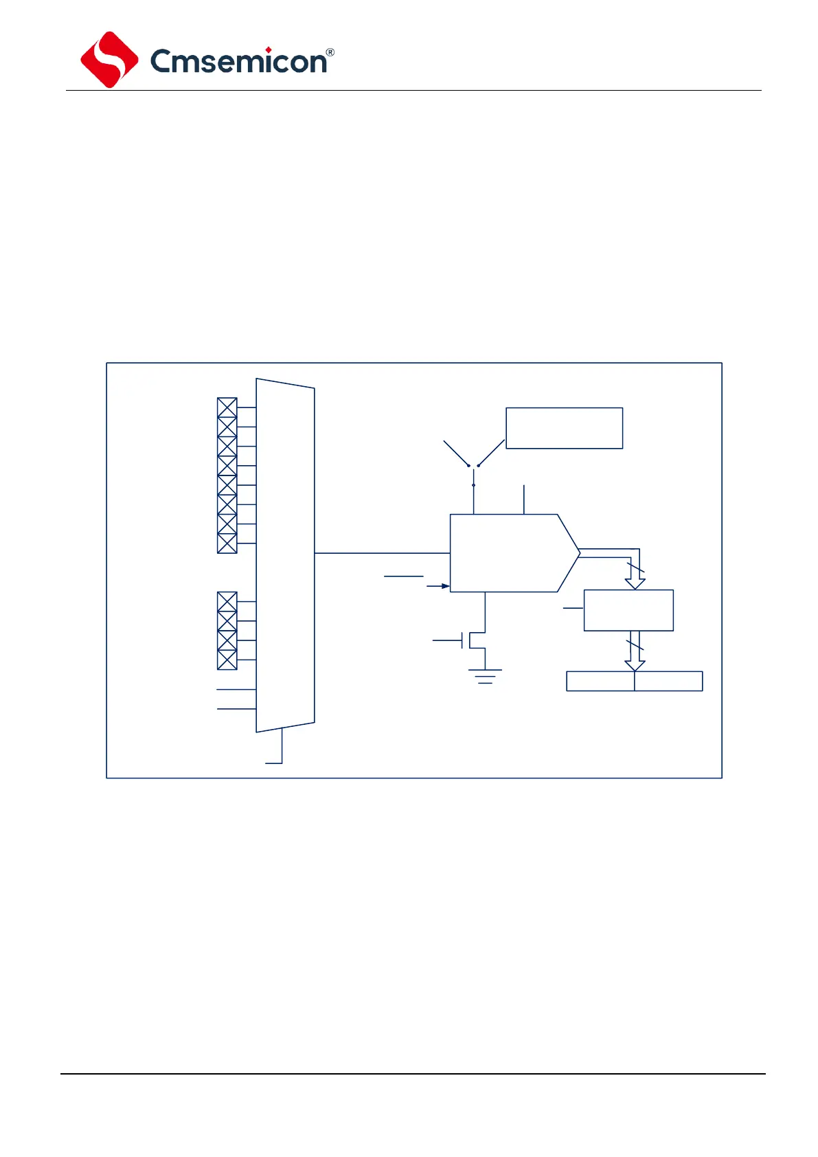
The analog-to-digital converter (ADC) can convert the analog input signal into a 12-bit binary number that
represents the signal. The analog input channels used by the device share a sample and hold circuit. The
output of the sample and hold circuit is connected to the input of the analog to digital converter. The analog-
to-digital converter uses the successive approximation method to generate a 12-bit binary result, and save
the result in the ADC result register (ADRESL and ADRESH).
ADC reference voltage is always generated internally. ADC can generate an interrupt after conversion is
completed.