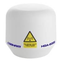
HGA-6000 High Gain Antenna
Installation Manual
Document: 862-A0059_IM issue 1.7 COMPANY CONFIDENTIAL
Page 5 of 37
L
IST OF FIGURES
PAGE
Figure 1 : Block diagram of HGA-6000 in a SATCOM system ........................................................ 8
Figure 2 : HGA-6000 & Slimline HGA-6000 High Gain Antennas ................................................... 9
Figure 3 : HGA-6000 bottom view ........................................................................................... 10
Figure 4 : HGA-6000 side view ................................................................................................ 11
Figure 5 : Slimline HGA-6000 bottom view ............................................................................... 12
Figure 6 : Slimline HGA-6000 side view ................................................................................... 13
Figure 7 : HGA-6000 Alignment marking from the base of antenna ............................................ 20
Figure 8 : HGA-6000 Inspection Criteria and Damage Limits ...................................................... 24
Figure 9 : Cobham SwiftBroadband System using SRS-7200 AHRS System ................................. 28
Figure 10 : Cobham SwiftBroadband System using IRS System ................................................. 28
Figure 11 : SwiftBroadband SATCOM System using HLD and IRS Navigation System ................... 29
Figure 12 : ARINC 741 SATCOM System using IRS Navigation System ....................................... 29
LIST OF TABLES
PAGE
Table 1 : HGA-6000 L-Band RF connector ................................................................................ 15
Table 2 : HGA-6000 Electrical Interface ................................................................................... 16
Table 3 : Standard HGA-6000 Data and power cable connectors ................................................ 16
Table 4 : HGA-6000 Equipment Required ................................................................................. 18
Table 5 : Test Equipment Required for HGA-6000 system installation ......................................... 18
Table 6 : HGA-6000 Inspections and Actions ............................................................................ 24
Table 6-1: Discontinued Products ............................................................................................ 25
LIST OF APPENDICES
PAGE
Appendix A:
Examples of Installation Configurations ............................................................ 27
Appendix B: Antenna Support Software Guide ..................................................................... 30
 Loading...