Do you have a question about the COBHAM HGA-7001 and is the answer not in the manual?
Provides overview of HGA-7001, its compliance standards, and approved SATCOM systems.
Lists and defines acronyms and technical terms used throughout the manual for clarity.
Details critical warnings, cautions, and notes for safe operation and installation practices of the antenna.
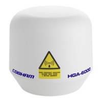
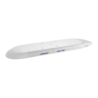
Presents top and bottom visual representations of the HGA-7001 antenna for identification.
Details the HGA-7001 as an ARINC 781 compliant phased array SATCOM antenna with integrated beam steering.
Lists key physical and equipment specifications, including environmental categories per RTCA/DO-160E standards.
Describes the HGA-7001's power source, interface protocols, and mechanical construction details.
Explains the electrical characteristics and functionality, including RF and data interfaces of the antenna.
Details RF and data connections, including specific connector types and pin assignments for system integration.
Describes how the system receives commands and reports status via ARINC 429 interface from the SDU.
Explains how faulty units are identified using internal Built-In-Test Equipment (BITE) codes and error reporting.
Provides recommendations for storing the HGA-7001, including required environmental conditions like temperature and humidity.
Outlines safe handling practices and the reuse of original packaging for transporting the HGA-7001 unit.
Details essential checks to be performed on the shipping container before the HGA-7001 unit is unpacked.
Lists checks to verify the unit's condition and completeness, including documentation and protective caps.
Provides instructions to verify all contents against the packing list to ensure the container is complete.
Covers the introduction to mounting, ideal placement, and alignment factors for the HGA-7001 on the aircraft fuselage.
Addresses lightning strike rating, RF blockage, co-location with other antennas, and engine inlet placement.
Details ground plane requirements, structural modifications, and weight considerations for mounting the antenna.
Covers painting, sealing, grounding methods, PIM compliance, and associated electrical requirements for installation.
Covers alignment tolerances, fuselage radius, speed limits, and required measurement accuracy for installation.
Details the step-by-step process for installing the antenna, including O-rings, bolts, and connecting cables.
Details the sequential steps required to safely detach and remove the antenna from the aircraft fuselage.
States that the HGA-7001 requires no routine maintenance or adjustment, only periodic inspection.
Instructs that faulty units are considered LRUs and must be returned to the supplier for service.
Introduces the section that lists specific tools, fixtures, and equipment required for HGA-7001 installation.
Lists specific tools, fixtures, and equipment necessary for installation, noting that equivalent substitutes may be used.
Introduces the Illustrated Parts List, specifying it is for a WHITE antenna and referencing supplier for other colors.
Explains the structure and usage of the Numerical Index and Detailed Parts List for identifying antenna components.
Details the columns and content of the Numerical Index, including part numbers, figures, and quantities required.