HGA-7001
Installation Manual
Document: 862-A0089_IM issue 1.6
COMPANY CONFIDENTIAL
Page 25 of 45
antenna attitude angles (relative to the same local level). The aircraft attitude
angles can be read from the ADI or measured with an electronic surface angle
protractor/inclinometer on an appropriate reference surface. The antenna attitude
angles can be measured by placing the protractor/inclinometer on the mounting
plate before the antenna is mounted.
(b) Lightning Strike
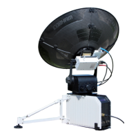
The HGA-7001 is rated for use in Zone 2A – swept strike zone. (Refer to paragraph
2.2).
(c) RF Blockage
1) Aircraft surfaces that interrupt the direct line of sight between the antenna and
satellite will cause a variable amount of blockage of the antenna RF beam.
2) The HGA-7001 should be mounted in a position that minimizes blockage by metallic
aircraft surfaces under normal operating conditions. Generally, it is best to mount
the antenna on the forward section of the fuselage. This typically minimizes
blockage caused by the tail and wings.
3) Figure 10 shows an example of RF blockage caused by the aircraft wing. In the
same manner, momentary blockage can be caused by the aircraft tail passing
through the satellite path.
 Loading...