HGA-7001
Installation Manual
Document: 862-A0089_IM issue 1.6
COMPANY CONFIDENTIAL
Page 14 of 45
Table 7: Equipment Specifications (Sheet 3 of 3)
Characteristic Specification
Beam switching < 50 microseconds between adjacent beams
Phase discontinuity < 12° for 99% of adjacent beam combinations
Carrier to multipath < 13 dB at 5° elevation < 18 dB at 20° elevation
Maximum input power 80 Watts average
Polarization Right-hand circular
Impedance 50 Ohms
VSWR < 2.0:1 transmit and receive
ELECTRICAL
Power consumption < 12 Watts
ELECTRICAL INTERFACE
Control and BITE ARINC 781
MECHANICAL
Weight 9.3 kg (21 lbs) Max
Size [L x W x H] 1050 mm x 299 mm x 51.6 mm
(41.34” x 11.77” x 2.03”)
2.3 Equipment Description
The HGA-7001 is powered with 115 V AC or 28 V DC (not qualified) aircraft power. The communications
interface between the HGA-7001 and the SDU is through an ARINC 429 protocol.
2.3.1 Mechanical Description
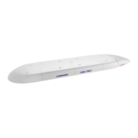
The HGA-7001 High Gain Antenna consists of an aluminium baseplate housing a 34 segment
radiating element array, a power supply, antenna control/driver assembly, and an integrated beam
steering unit. The internal components are protected by a composite radome bonded to the
baseplate. The antenna must always be mounted to the aircraft via a mounting / adaptor plate
which is manufactured for a specific aircraft and/or fuselage diameter.
Electrical connection to the antenna is made through a MIL-C-38999 13-pin connector. The RF
connection is via a female TNC connector. For electrical bonding a ground stud or threaded hole
may be provided (dependent on aircraft configuration). The electrical connections are accessible
at the rear of the antenna via a removable Tail Cap.
Figure 2 shows the top side of the antenna with the eight sealing caps (1) removed and the Tail
Cap (2) attached.
 Loading...