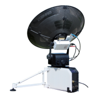
HGA-7001
Installation Manual
Document: 862-A0089_IM issue 1.6
COMPANY CONFIDENTIAL
Page 30 of 45
5.8 Mounting and Removal Procedures
5.8.1 Limitations and Alignment
(1) If necessary, the fore/aft axis shall be measured to within ±0.25° of the aircraft’s longitudinal
axis and the roll and pitch angles measured to within ±0.25°.
(2) The mounting/adaptor plate used must be correct for the radius of the aircraft fuselage.
Contact supplier for details.
(3) The maximum rated speed is 355 KEAS or Mach 0.92. At this speed the antenna is well within
its structural limits, and therefore, more extreme flight envelopes are possible. Contact the
Supplier for more information.
5.8.2 Mounting Procedure
(1) Ensure the O-rings [IPL 18-40] are in place on the base plate of the antenna around the
mounting points. Base plate O-ring seals should only be replaced if visibly damaged; they can
be pried out with any sharp object and easily replaced by hand.
(2) Ensure that the mounting surfaces on both the antenna and adaptor/mounting plate are clean
and free from any foreign matter.
(3) Align the HGA-7001 with the mounting holes.
CAUTION: AVOID SLIDING THE ANTENNA ON THE MOUNTING/ADAPTOR PLATE SINCE IT MAY
DAMAGE THE BOTTOM O-RINGS AND PAINT SURFACES.
(4) Insert the mounting bolts. First fit all the bolts loosely, before tightening down evenly to 3.5
– 5 Nm (2.6 – 3.7 ft-lb). The tightening sequence should be from the centre outwards. See
installation drawing Doc No. 677-A0173_ID for locating dimensions.
CAUTION: IF THE MOUNTING BOLTS ARE TOO LONG, THERE IS THE RISK OF BREACH OF THE
PRESSURE VESSEL OF THE AIRCRAFT, AS THE SEALED ANCHOR NUT COVERS MAY
BE RUPTURED.
(5) If the grounding method is by means of a ground strap attached to the ground stud provided
in the connector area, this strap should be attached to the antenna at this point.
(6) Attach the free end of the ground strap (if used) to the fuselage.
(7) Connect the RF Interface (TNC) and Control and Data Interface (MIL) connectors of the
cables protruding from the fuselage penetration to the antenna. (Refer to Figure 12 below).
 Loading...