HGA-7001
Installation Manual
Document: 862-A0089_IM issue 1.6
COMPANY CONFIDENTIAL
Page 15 of 45
Figure 2: Top Side of Antenna
2.3.2 Electrical Description
The HGA-7001 is an ARINC 781 compliant low-profile, electronically steered SATCOM antenna,
using patented phased-array beam forming technology. It performs both transmit and receive
functions. The HGA-7001 contains an integrated BSU that receives commands in the ARINC 429
format.
A multi-pin connector is provided in the connector compartment for direct connection to aircraft
power, the DLNA and the SDU interface cable.
2.3.3 System Interconnection
Refer to Figure 3 and Table 8 for pin assignments of the multi-pin connector and the HGA-7001
Wiring Diagram for system interconnections. Refer to Figure 4 for a diagram of antenna
connectors.
(1) RF Interface (Female TNC connector)
The suggested mating connector is dependent on the type of low loss cable used. Low loss
cables with different diameters may require different connectors. The connector and cable
should be of low PIM specification, as recommended in ARINC 781. Contact the Supplier for
information on availability of a PIM free cable for SwiftBroadband use.
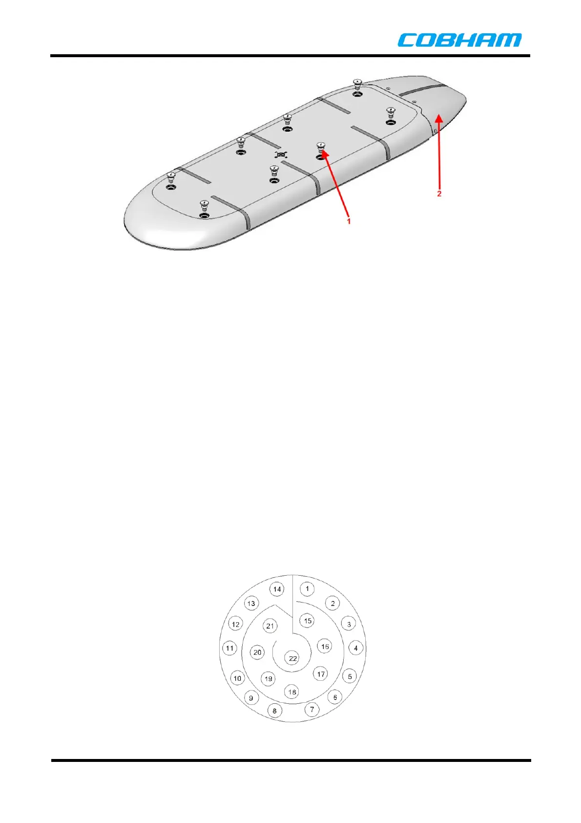
(2) Power and Data Interface (Multi-Pin Connector)
The multi-pin connector consists of a 13-35 insert of the MIL-C-38999 Series III family in a
hermetic box mount, part number D38999/21YC35PN. Suggested mating connector is
D38999/26SC35SN or equivalent.
Figure 3: Multi-pin Connector Pin Numbers
 Loading...