Chapter 1: Introduction
6 System components
• Easy installation with the dedicated connection box available (SAILOR
6283 AIS Connection Box and Wall Tray)
• Easy service - on the unit, through the ThraneLINK Management
Application (TMA) or a web browser
• Built-in self-diagnostic system
• Built-in DC output on GPS antenna connector
• Possibility for a combined VHF and GPS antenna
• River use compliant with CCNR requirements
• Works with both GPS and GLONASS
• Input for Low Power Forced Control, 1W output (gas alarm)
• Support of Class B carrier sense messages
• Function for discarding Class B messages
• Support for Long Range satellite tracking on channel 75 & channel 76
• Interface for pilot plug
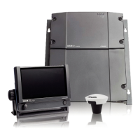
System components
SAILOR 6282 AIS Transponder
The SAILOR 6282 AIS Transponder is a combined Class A and Inland AIS
station. It has connectors for GPS and VHF antenna, a ground stud,
connector for DC power (12–24 VDC), multi connector for interfaces and
2 LAN connectors. The SAILOR 6282 AIS Transponder is always on,
provided there is DC power.
The SAILOR 6282 AIS Transponder supports 3 sensor inputs for e.g. GPS
and ROT and 4 presentation interfaces for e.g. ECDIS, Radar, Long Range
and Pilot Plug. It also has inputs for Blue Sign functionality, Low Power
Forced Control (gas alarm) and output for alarm. The SAILOR 6282 AIS
Transponder has three LEDs showing the status of Power, Rx and Tx.