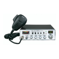
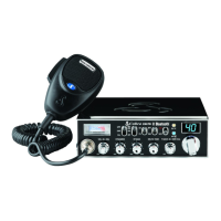
S-MTR EXT.SP.
+ POWER –
Ignition Noise Interference
Antennas
Use of a mobile receiver at low signal levels is
normally limited by the presence of electrical
noise. The primary source of noise in automo-
biles is from the alternator and ignition system.
Typically, when signal level is adequate, the back-
earth noise does not present a serious problem.
Also, when extremely low level signals are being
received, the transceiver may be operated with
the vehicle’s engine turned off. The unit requires
very little current and therefore will not signifi-
cantly discharge the vehicle’s battery.
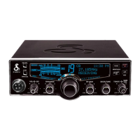
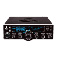
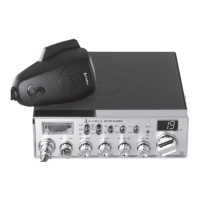
Even though the Cobra 29 LX EU has an auto-
matic noise limiter, in some installations ignition
interference may be high enough to make good
communications impossible. Many possibilities
exist and variations between vehicles require
different solutions. Consult your Cobra dealer or
a 2-way radio technician for help in locating the
source of a severe noise.
CB Antenna
Since the maximum allowable power output of
the transmitter is limited, the antenna is critical in
affecting transmission distance. Only a properly
matched antenna system will allow maximum
power output. Cobra loaded type antenna models
are highly recommended for most installations.
Marine Installation
The transceiver will not operate at maximum
efficiency in a boat without a ground plate,
(unless it has a steel hull). Before attempting
installation , consult your dealer for information
regarding an adequate earthing system and pre-
vention of electrolysis between fittings in the hull
and water.
CB Antenna
7
Note
Foroptimumperformancein
passengercarstheidealanten-
nalocationisonthecentreof
theroof.Secondchoiceisonthe
centreoftheboot.
Note
Becausemanynewertrucks
featurefibreglassdoorskins,
theoutsidemirrormustbe
earthedtothechassisviaa
earthstrap,iftheantennais
mountedonthemirrorbracket.
Note
3-wayCombinationAntennas
arealsoavailable,whichallow
operationofallthreebands
(AM-FM&CB),usingasingle
antenna.However,thistype
ofantennausuallyresultsin
lessthannormaltransmitand
receiverangewhencompared
toastandard-type“Single
Band”CBantenna.
6
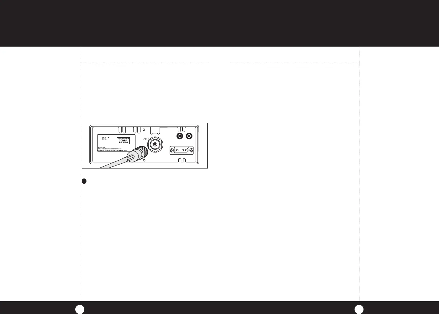
1
A standard antenna connector is provided
on the transceiver for easy connection.
29LXEU_MANL_ENG_vD.indd 6-7 1/11/12 10:09 AM
 Loading...