8525B/8528 Technical Service Manual General Information 1-7
Publication No: 15-02036 Issue 6
ALC A 10dB increase in input level above
compression threshold produces less
than 0.5dB increase in power output.
Maximum ALC range greater than 30dB.
ALC attack time approximately 1ms.
Residual Noise 65(55)dB below PEP in 3kHz channel.
Transmitter Noise
Floor
Transmitter noise output below cut-off
frequency of harmonic filter in 3kHz
bandwidth typically −67dBm.
Microphone Dynamic type with push-to-talk switch
fitted in case.
1.2.4 Rear Panel Connectors
The following tables show the pin connections, functions, and signal levels
for the rear connectors.
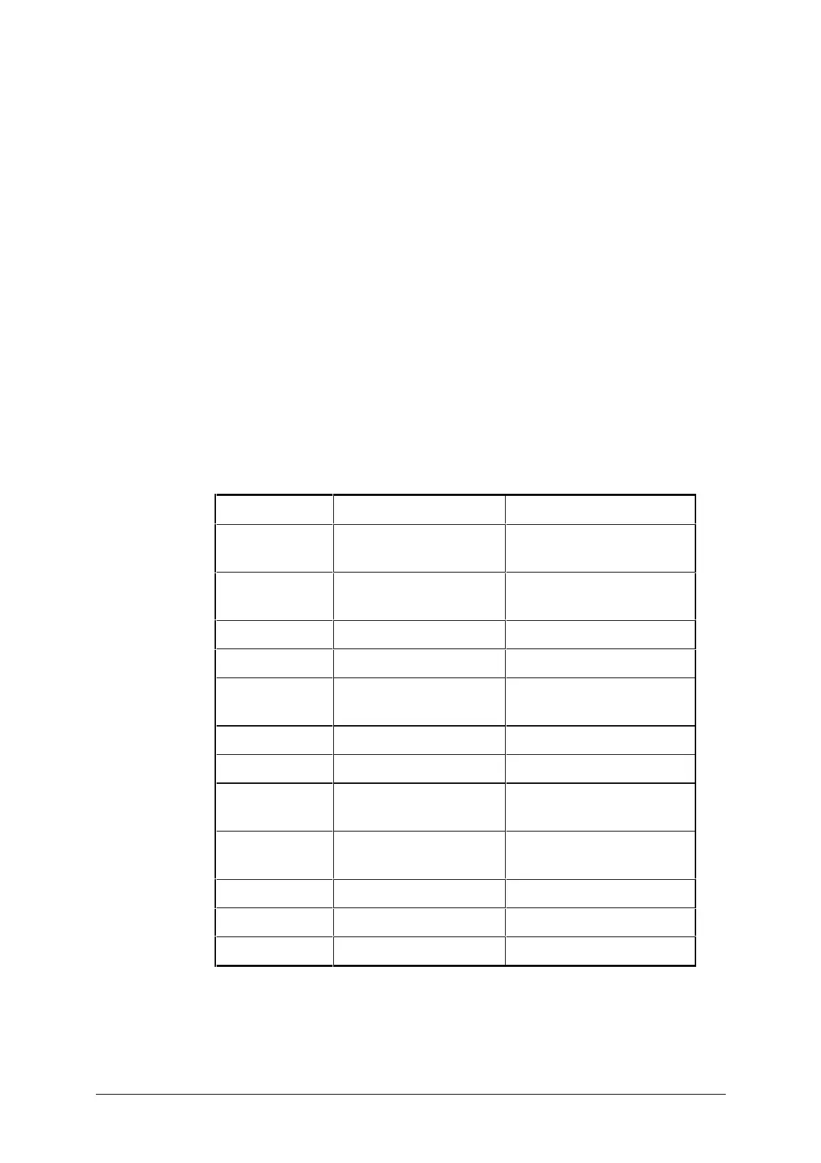
Antenna Select Facility (15-way, D-type Socket)
Pin Number Function Signal Level
1 Channel Number Bit
3
Logic (Open Collector)
2 Channel Number Bit
4
Logic (Open Collector)
3N/C
4 TUNE IN/OUT 5V Logic (Active Low)
5 SCAN (Active
Antenna)
Logic (Open Collector)
6 & 7 N/C
8 PTT out +10V (1kΩ source)
9 Channel Number Bit
1
Logic (Open Collector)
10 Channel Number Bit
2
Logic (Open Collector)
11 TUNED IN 5V Logic (Active Low)
12 & 13 A rail + Battery supply out
14 & 15 0V Ground
N/C = Not Connected
All channel number bits active high. (Pull-up resistors required).