6-6 Maintenance 8525B/8528 Technical Service Manual
Issue 6 Publication No: 15-02036
6.2.3 Front Panel Controls
IN THE TEST WHICH FOLLOWS CARE MUST BE TAKEN WHEN
MAKING CONTACT WITH THE CONNECTIONS TO THE SWITCH
SUBSTRATE NOT TO SCRATCH THE SILVER PLATING.
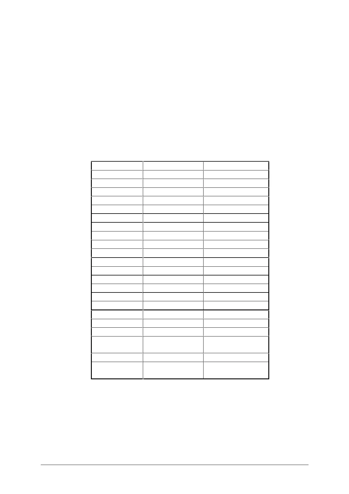
Lack of response to controls may be due to malfunction of one or more of
the sealed membrane switches. These can be tested by disconnecting the
connector from the front panel (or control head) switches at J4 on the
Display PCB and testing between pins of the connector as shown in the table
below. A meter connected between each pair of pins in turn should indicate
open circuit with the corresponding switch not operated and continuity (less
than l00Ω) when the switch is pressed.
Front Panel Switch Test (8528)
Connector Pin 8528S 8528
1 - 2 Mute On/Off Mute On/Off
1 - 4 Scan Scan
1 - 5 AM Mode S’call Mute
1 - 7 Tx Power USB/LSB
1 - 8 Power On/Off Power On/Off.
1 - 10 Tune Tune
3 - 2 2182 Display
3 - 7 Enter Enter
3 - 8 – Emgcy Call
3 - 10 Recall Recall
6 - 2 Volume (up) Volume (up)
6 - 4 Clarifier(up) Clarifier (up)
6 - 5 Channel (up) Channel (up)
6 - 7 Tune Rx (up slow) Tune Rx (up slow)
6 - 8 Call (red) -
6 - 10 Tune Rx (up fast) Tune Rx (up fast)
9 - 2 Volume (down) Volume (down)
9 - 4 Clarifier (down) Clarifier (down)
9 - 5 Channel (down) Channel (down)
9 - 7 Tune Rx (down
slow)
Tune Rx (down slow)
9 - 8 Test Call
9 - 10 Tune Rx (down
fast)
Tune Rx (down fast)