http://www.coef.it - info@coef.it Pag. 15
10.2 ELETTRONIC MAINTENANCE
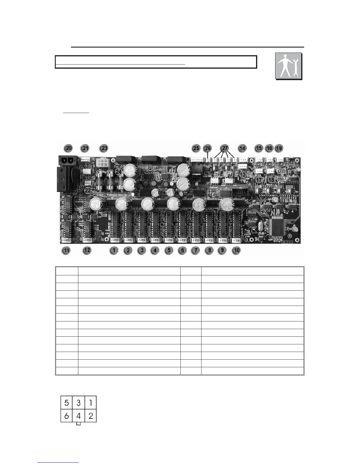
Thissection isdedicated in detail to theelectronic connectionsbetween thecard and the mecha
-
nical components, assembled in theprojector. These informations will beabsolutely necessary when
the mechanicalunit has to be removed from theprojector fo
r maintenance and/orrepair.
The connections aremade usinghandy connectors and are detailed in figurewhere you can find indications
aboutthe connection between a specific connector and a specific component of the mechanicalunit.This includes
the motors and the sensors of the various effect
s wheels ( color, gobos, prisms, shutter etc.).
WARNING!
An improper use of this documentation made by not specifically qualified staff can damage
irremediably the electronic and/or mechanical components of the projector.
1
MotorSHUTTER / STROBE 15 Sensor PAN
2Motor COLOREwheel16Sensor TILT
3Motor GOBOS wheel17S1Sensor COLOR wheel
4Motor GOBOS Rotation 18 S2 Sensor GOBOS wheel
5Motor EFFECTS wheel19S3Sensor GOBOS Rotation
6Motor ZOOM 20 ON/OFF Lamp (only Magnetic Ballast version)
7Motor FOCUS 21 Electronic
Ballast connector
8MotorCONVERSION FILTERS 22 LIGHTSensor / NTC Sensor
9Motor IRIS 23 POWERConnector
10 Motor PRISM Rotation 24 Faston GROUND connection
11 Motor TILT 25 DMX IN/OUT
12 Motor PAN 26 Head FAN
13 Encoder TILT 27 Base FAN
14 Encoder PAN
WARNING: switch off the projector before operating
23 - Power connector on board
1-2 12V~ +/- 5% Blue
3-4 27V~ +/- 5% Grey
5-6 27V~ +/- 5% Black
 Loading...