Installing the In-Sight 2000
13
Discrete I/O Specifications
In addition to the built-in trigger input and strobe output on the camera (page 20), In-Sight also
provides up to ten discrete inputs and ten discrete outputs for general-purpose use. Two inputs
and two outputs are built into the In-Sight processor, which provides optical isolation for the
signals. The remaining eight inputs and outputs require the optional I/O Expansion Module.
Each discrete I/O signal is electrically independent. By default, polarity is active-high, so the
transition from 0 to 24 VDC indicates ON. You can invert the polarity (to active-low) through
In-Sight's Discrete Input and Discrete Output dialogs.
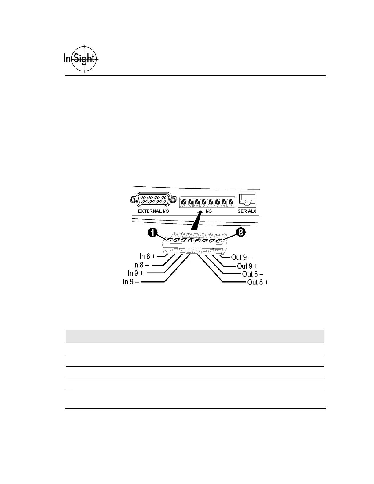
Connect the built-in discrete I/O through a detachable 8-pin plug (Cognex P/N 182-0463 or
Phoenix Connector #1803633) as shown in Figure 4.
Figure 4. I/O Port Pin Numbers
Table 3 contains the signal name for each pin labeled in Figure 4.
Table 3. I/O Pin Numbers and Assignments
Pin Signal Name Pin Signal Name
1 IN 8 + 2 IN 8 –
3 IN 9 + 4 IN 9 –
5 OUT 8 + 6 OUT 8 –
7 OUT 9 + 8 OUT 9 –