Installing the In-Sight 2000
20
Trigger and Strobe Output Specifications
To activate the on-camera trigger, apply a transition voltage to the trigger input. The transition
voltage should be from the range 0.0-0.8 VDC to the range 3-24 VDC.
To trigger a strobe device, the camera generates a strobe output signal when it is ready to
integrate light. The signal is a 10-mA pulse with a duration of about two horizontal scan lines
(128 µsec). During this interval, the camera's optocoupler switch is closed. The device to be
activated should be optically isolated.
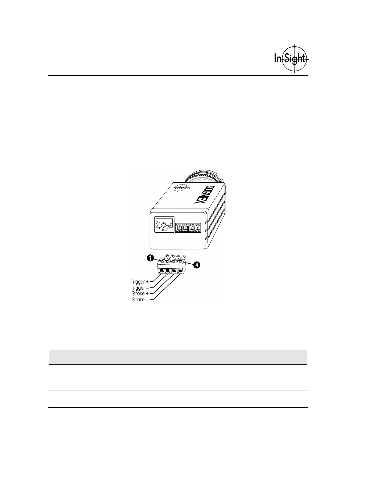
Figure 10 provides trigger input and strobe output pin numbers and assignments.
Figure 10. Trigger Input and Strobe Output Pin Numbers
Table 7 contains the signal name for each pin labeled in Figure 10.
Table 7. Trigger Input and Strobe Output Pin Numbers and Assignments
Pin Signal Name Pin Signal Name
1 Trigger + 2 Trigger –
3 Strobe + 4 Strobe –